English
A plant engineer sends over one worn aluminum bushing: 40 mm OD, 32 mm H7 bore, 45 mm long, a 6 mm flange, and two annular grease grooves. It ran on a hardened 32 mm steel shaft in a packaging line at roughly 300 rpm until the bore went oval and the line started to chatter at start-up. The replacement order is 20 pieces, and the machine shop comes back with three questions: what clearance, what alloy and temper, and does the groove geometry stay the same. Those three answers decide whether the replacement runs a year or seizes in six weeks.
Here is the short version before the detail. In custom aluminum bushing machining, the bore and the running clearance control most of the outcome. Alloy and temper, wall thickness, coating, and lubrication geometry follow from the load, the speed, and whether the joint ever sees grease. Get the bore wrong and even a perfectly round, beautifully finished part will fail.
Content
The Bore Defines the Fit; Everything Else Follows
Running clearance is the first number to fix. A dry or lightly greased aluminum bushing on a hardened steel shaft usually needs 0.02–0.05 mm of diametral clearance in the 20–60 mm range. Below 0.02 mm the aluminum picks up on the shaft and the bore scuffs within hours. Above 0.08 mm the bushing starts to hammer, the bore goes oval, and vibration shows up as noise in the assembly.
Where the bushing presses into a housing, the interference is a separate calculation. Into a steel or cast iron housing, 0.02–0.05 mm interference on a 40 mm OD is normal practice. Into an aluminum housing, push it to 0.04–0.06 mm, because the softer housing yields first and a light press-fit works loose after a few thermal cycles.
Concentricity matters more than many drawings admit. If the ID and the OD are not concentric within roughly 0.015 mm TIR, the wall thickness varies, one side of the bore carries the load, and wear turns oval instead of even. That is exactly what happened to the 32 mm bushing described above.
Thermal growth is the factor people forget. Aluminum expands at about 23 × 10⁻⁶ per kelvin, steel at about 12 × 10⁻⁶. On a 40 mm diameter running 60 °C above assembly temperature, the aluminum part grows roughly 0.026 mm more than the steel shaft. If clearance was set at 0.02 mm cold, it is gone by the time the machine reaches operating temperature.
Alloy and Temper: Choose for Wear, Not for Strength
Aluminum bushings are rarely strength-limited; they are wear- and clearance-limited. That single fact re-orders the material list. A higher-strength alloy does not buy wear resistance, so the sensible default for a general-purpose bushing is 6061-T6, with the harder, more corrosion-sensitive alloys reserved for specific conditions.
| Material | Typical bushing role | Machining behavior | Wear and environment notes |
|---|---|---|---|
| 6061-T6 | General-purpose bushings, spacers, flanged sleeves up to about 80 mm OD | Free-cutting, stable, holds tight bores well | Moderate wear resistance; needs grease or hard anodizing for continuous sliding |
| 6082-T6 | Same duties as 6061 when metric bar stock is preferred | Similar to 6061, slightly stronger, good chip control | Comparable wear; anodizes uniformly |
| 2024-T4 | Higher-load bushings in dry, protected environments | Machines to a fine finish, stringy chips, needs care on thin walls | Poor corrosion resistance; not for wash-down or humid service |
| 7075-T651 | Thin-wall, high-load bushings where space is fixed | Higher cost, more tool wear, notch-sensitive under shock | Best strength of the common alloys; still limited sliding wear without coating |
| Aluminum bronze (C932) | Unlubricated, high-load pivots and slow oscillating joints | Slower cutting, three times the density, higher material cost | Far better load capacity and wear life; the correct fallback when grease is impossible |
One coating detail catches people out. Hard anodizing (Type III) grows the surface by roughly 25–50 µm per side, so a bore machined to 32.00 mm can close to 31.90 mm after coating. The plating thickness has to be written on the drawing and machined undersize on purpose, not discovered at assembly.
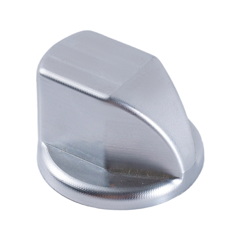
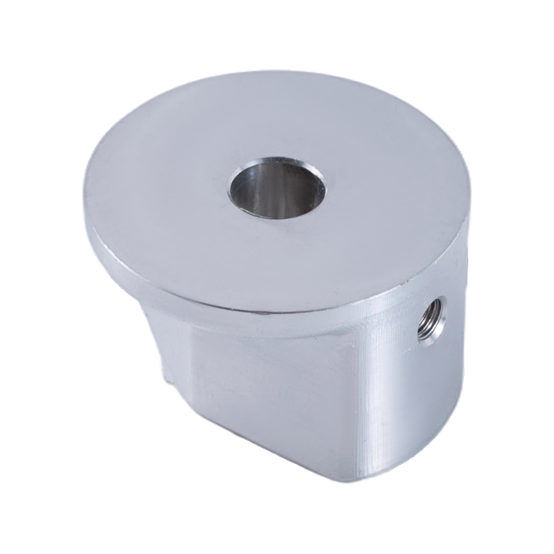
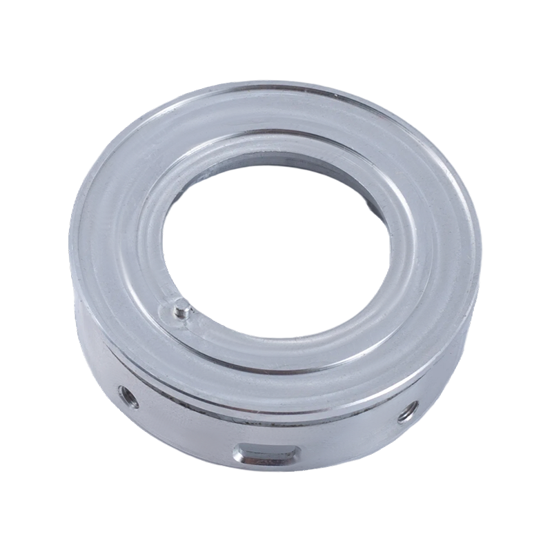 Lightweight Aluminum CNC Turned Bushing and SleeveA lightweight CNC-turned bushing for weight-sensitive assemblies, with anodizing and machining guidance useful when checking coating, wall thickness, and custom features.View Product →
What "Custom" Actually Changes on the Shop Floor
Custom work on bushings is driven by features, not by diameter. A plain 40 mm sleeve with a single bore is a short setup. Add a flange, two oil grooves, a cross-drilled lubrication hole, and a snap-ring groove, and the part moves through four or five more operations, each with its own fixturing and inspection.
Tolerances that change the process
- Bore tolerance tighter than ±0.010 mm usually moves the job from reaming to fine boring, with temperature-controlled measurement and plug gauges.
- Wall thickness under about 3 mm calls for soft jaws or an expanding mandrel; standard three-jaw chucking will squeeze the part oval and it springs back after release.
- Concentricity tighter than 0.010 mm TIR normally means a single setup, or a between-centres operation rather than turning the part twice.
Features that add real cost
- Annular or spiral grease grooves, which need a form tool or a dedicated grooving cycle.
- Cross-drilled holes intersecting the bore, which require deburring and often a small chamfer to protect the shaft.
- Flange faces that need to run square to the bore, since a flange that sits proud tilts the whole bushing in its housing.
- Keyways, snap-ring grooves, and lubrication flats, each adding a separate operation and inspection point.
For parts that combine a locating shoulder, a flange, and a precision bore in one piece, the geometry is not unusual and the tolerances are achievable, but the quote should list the setups so you can see where the cost sits. The bushings and sleeves range covers these combined forms in both plain and flanged configurations.
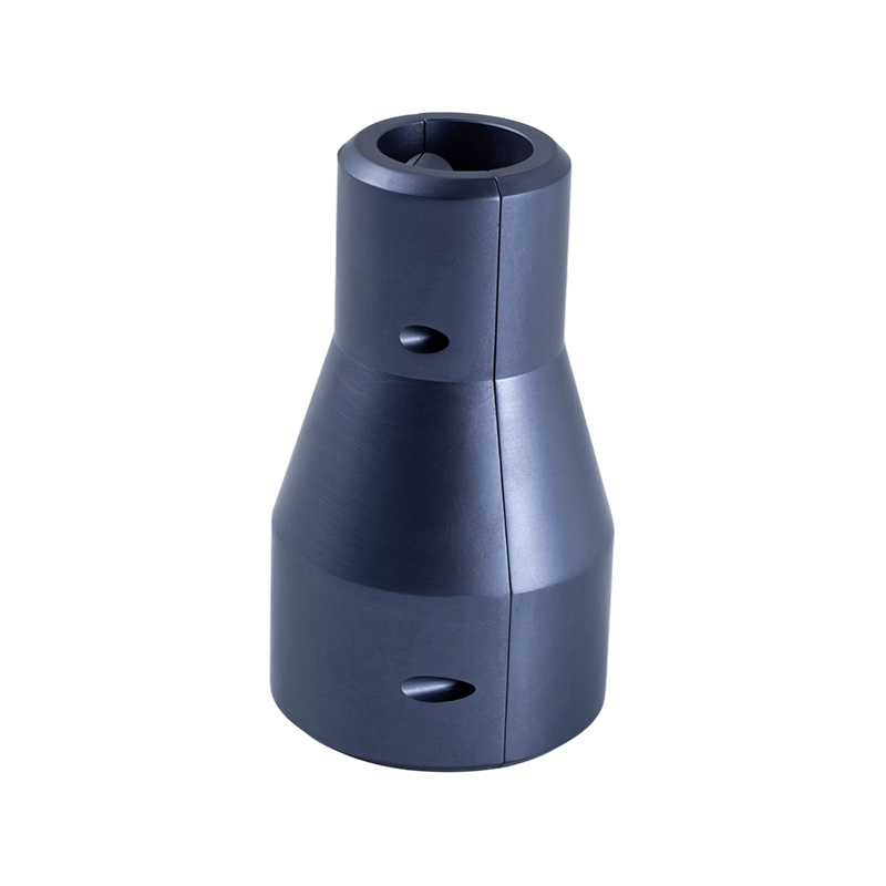 Integrated Flange Bushing for Radial Support and Axial FixationOne-piece CNC-turned flange bushing that combines sleeve and flange to reduce assembly interfaces, concentricity error, and loosening compared with separate retaining-ring setups.View Product →
Drawing and Sample Inputs That Prevent Rework
A complete request for quotation removes almost all of the back-and-forth. The parts that arrive with full information get quoted in a day; the ones with a hand sketch and one dimension get quoted twice and then reworked once.
- Material and temper, including whether anodizing or plating is required and on which surfaces.
- Quantity and batch split, for example 5 prototypes plus 50 production pieces, since small-batch prototype machining and volume turning are planned differently.
- Critical dimensions flagged, with the tolerance class stated explicitly rather than left to default.
- The functional datum scheme, so the machinist knows which feature locates the part in the assembly.
- Surface finish in Ra where the bore slides, and the edge-break requirement on every chamfer.
- The working environment: radial load, sliding speed, temperature range, lubricant, and the mating shaft material and hardness.
- Mating bore size and fit class for pressed-in applications, including the housing material.
When only a worn sample exists, the process is measurement-led rather than drawing-led. Measure the original bore and OD, note where the wear pattern sits, and decide whether the replacement should restore the original clearance or correct a design that clearly ran too tight. Adding 0.03 mm of bore clearance on a part that scuffed on one side is a common and effective correction.
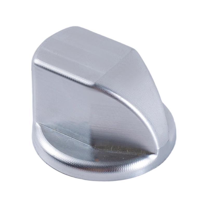 Custom CNC Machining from Drawings or SamplesA custom machining service producing parts from customer drawings or samples, suited to replacement bushings when dimensions and condition must guide the work.View Product →
Failure Modes and the Machining Fixes
Most aluminum bushing failures trace back to five causes, and each one has a machining or specification answer.
- Galling on the shaft: caused by insufficient lubrication or a tight clearance. Fix with grease retention grooves, a PTFE coating, or a switch to aluminum bronze.
- Oval bore after a few thousand cycles: caused by uneven wall thickness or excessive running clearance. Fix with tighter concentricity and a clearance at the higher end of the safe band for shock loads.
- Burrs at cross-drilled holes: caused by drilling directly into the bore without a deburr pass. Fix with a specified chamfer and a documented deburr operation.
- Press-fit push-out: caused by relying on friction alone in a soft housing. Add a shoulder, a retaining flange, or switch to a light interference plus adhesive.
- Corrosion-driven seizure in humid or wash-down service: common with 2024 and 7075. Fix by specifying 6061 with hard anodizing, or moving to a bronze alloy.
Release the Order Only After These Checks
- Clearance verified at operating temperature, not only at assembly temperature.
- Coating thickness accounted for in the machined bore size.
- Wall thickness 3 mm or more, or the fixture method confirmed for thinner sections.
- Concentricity and roundness specified separately; roundness is what prevents oval wear.
- Lubrication path defined: grooves, cross holes, or a coated surface.
- Inspection method agreed, with bore gauges or a CMM report on the first article.
If the part also involves turning, milling, and grinding steps, it helps to review how tolerances and materials interact on turned components before the drawing is frozen; this overview of CNC turning tolerances, materials, and inspection practice covers the same fundamentals from the shop side.
Custom aluminum bushing machining rewards precision in the right places. Nail the bore, the clearance at temperature, and the lubrication path, and a 6061-T6 bushing will comfortably outlast the machine cycle it serves. Spend the extra tolerance budget on the flange and the outer cosmetics instead, and the part becomes expensive without becoming more durable.