

 English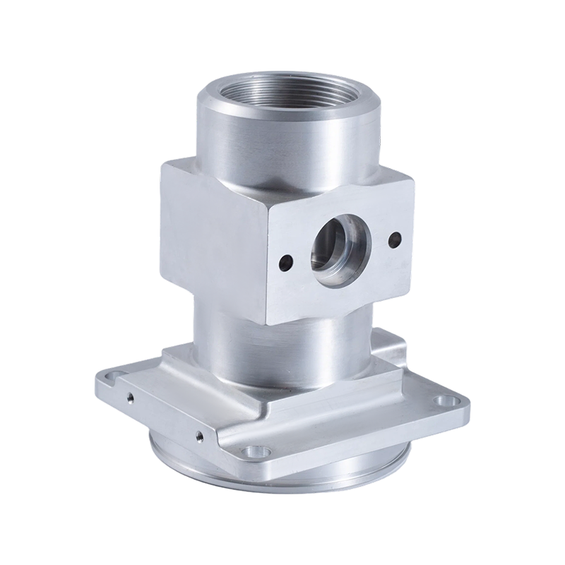
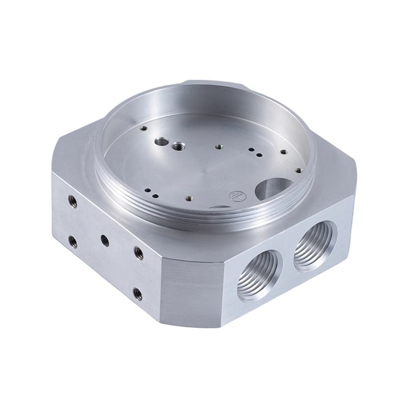
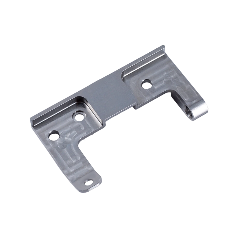
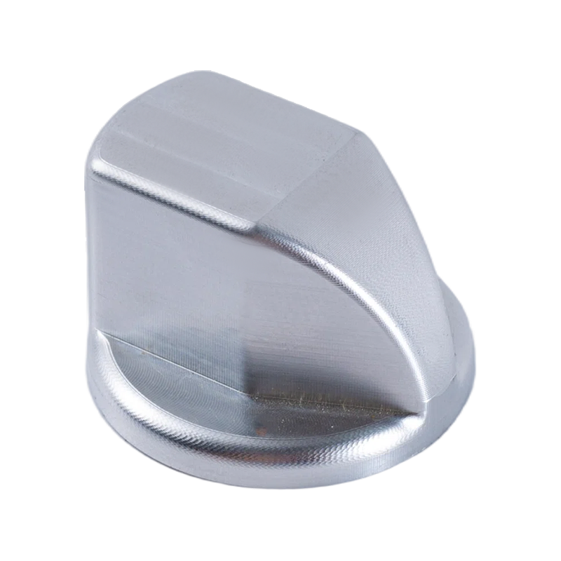
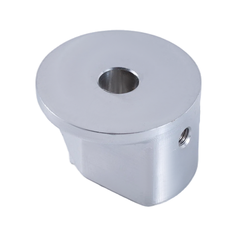
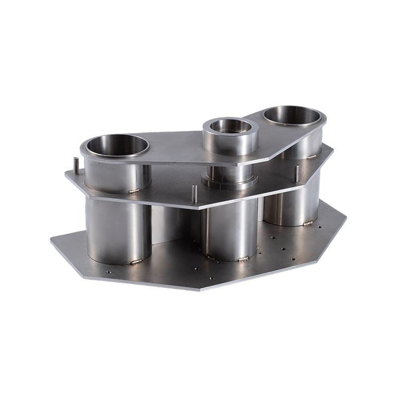
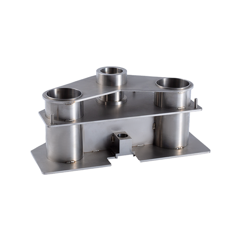
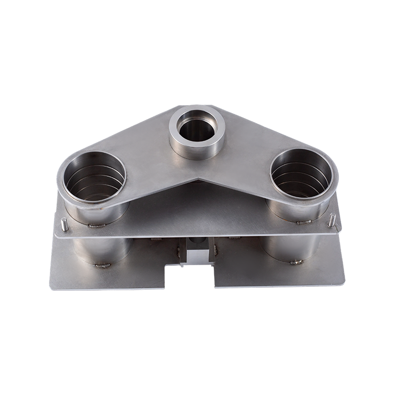
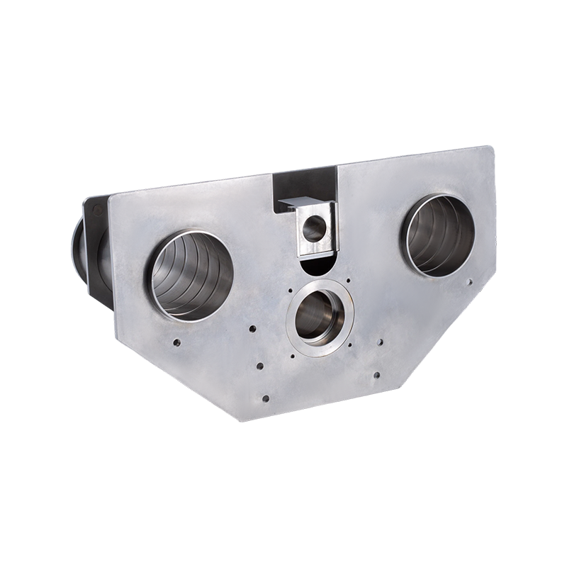


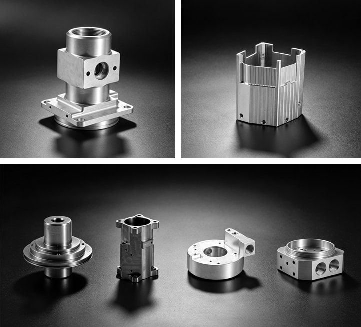
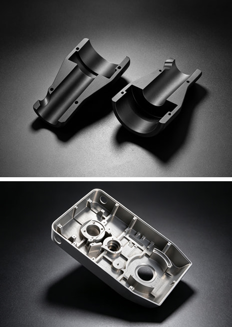
At Suzhou Miaocheng Precision Machinery Co., Ltd., we produce non-standard precision components from customer drawings, CAD models and physical samples. As a Custom Machining from Drawings/Samples manufacturer based in Suzhou, China, we work with procurement teams and engineers when a standard catalog part does not exist or when an existing component must be reproduced with controlled accuracy. Within our Custom CNC Machining range, this category handles parts defined by engineering drawings, 3D models or reference samples. Our scope covers precision component processing and module assembly, supported by dozens of 3-axis, 4-axis and 5-axis CNC machining centers, precision grinding machines and an ISO 9001:2015 quality system.
Since 2012, we have served customers in medical equipment, photovoltaic new energy, automotive, aerospace, semiconductor, food machinery and environmental protection. For this category, the common thread is not a single geometry but the need to machine high-difficulty, non-standard parts exactly as specified.
What Custom Machining from Drawings/Samples Covers
This category is for parts defined by engineering documentation or a reference part rather than a standard product range. It covers replacement components, modified designs, legacy parts, OEM parts and new production items where no catalog option exists. We do not require a full production drawing to start a conversation; when a physical sample is provided, we measure the relevant features and define a machining route that reproduces its function.
- Non-standard mechanical components with turning, milling, drilling, threading, grooving and contouring features.
- Multi-operation parts: a shaft with milled flats, a housing with precision bores, a bracket with complex hole patterns.
- Prototype, validation and production quantities, coordinated with our Small-Batch Prototype Machining service.
- Components that need module-level assembly after machining.
Because we operate both CNC turning and CNC milling cells plus grinding and CMM inspection, the drawing/sample category can absorb mixed-geometry parts that would otherwise require multiple suppliers. Typical examples include precision shafts, stepped shafts, micro shafts, bushings and sleeves, housings, enclosures, brackets, threaded connectors, valve bodies and fluid-control components.
How We Convert a Drawing or Sample into a Machined Part
Every custom project starts with the same question: which features determine function? The answer comes from the drawing, the 3D model or the sample. From there we select the machine type, workholding, tooling and inspection points.
| Project Stage | What We Work From | What the Customer Gets |
|---|---|---|
| Drawing review | 2D drawing with dimensions, GD&T and material callouts | Machinability confirmation, datum check and clarification list |
| Process planning | 3D model, tolerances, quantity and surface finish requirements | CNC turning or milling route, workholding plan and quotation |
| Sample evaluation | Physical sample and agreed measurement points | Feature verification and a basis for production drawing approval |
| Machining | Approved program, selected material and in-process checks | Parts produced on 3/4/5-axis CNC and precision grinding equipment |
| Inspection and delivery | Drawing tolerances, CMM data and final outgoing control | Conforming parts with inspection results controlled under our quality system |
Material and Specification Considerations
Material selection is part of the drawing review, not an afterthought. The product range includes stainless steel components, aluminum bushings and lightweight alloy structural parts, so the discussion normally covers grade, condition and supplied-material requirements before we finalize a process. For sample-based work, material information matters as much as geometry. We need to know the material, hardness, surface treatment or functional environment so the finished part matches not only the shape but the behavior of the original.
- Datum structure and how tolerances relate to mounting or mating surfaces.
- Wall thickness and unsupported features that may require specialized tooling.
- Thread position, depth and class.
- Surface finish and edge conditions such as deburring and radii.
- Quantity and repeatability expectations, because they affect workholding and inspection strategy.
Quality Assurance and Inspection
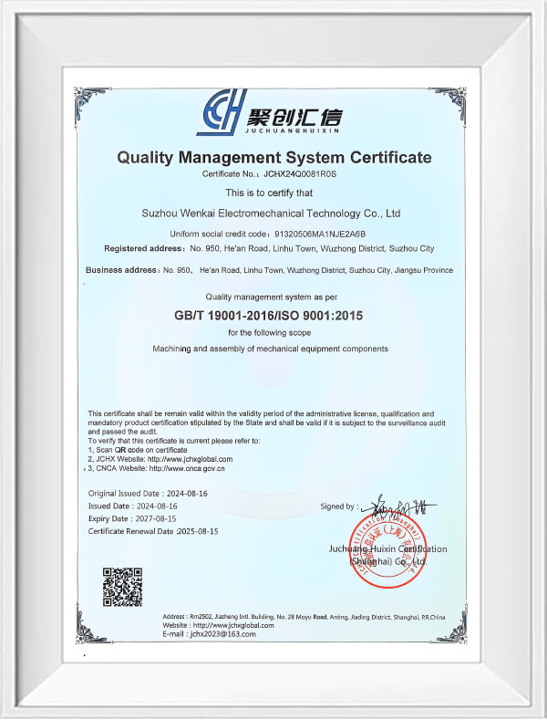
Quality is monitored from material receiving to final outgoing inspection. The company operates under ISO 9001:2015 and uses three coordinate measuring machines, precision height gauges and video measuring machines to verify custom parts. Raw material verification, in-process checks and final inspection are applied according to the drawing and agreed requirements.
For components with unusually tight tolerance or demanding geometry, we use our Ultra-High Precision Tolerance Machining capabilities. This category is closely linked to drawing/sample work because tolerances often cannot be evaluated until the drawing and sample are reviewed together.
Information We Use to Configure Your Solution
To prepare a meaningful process plan and quotation, we need as much of the following as the project allows:
- 2D drawing in PDF, DWG or image form, including dimensions, tolerances and general notes.
- 3D model in STEP, IGES or another standard CAD format.
- Physical sample, especially when original drawings are unavailable.
- Material grade and requested condition, or the material specification from the drawing.
- Annual quantity, order quantity and expected batch size.
- Critical dimensions, surface finish requirements and any coating, plating or marking requirements.
- Assembly, packaging or documentation requirements if the part is part of a supplied module.
If only a sample is available, we measure the relevant features, review the material and agree on a tolerancing approach before quoting. This avoids ambiguity when the original design intent is no longer documented.
Frequently Asked Questions
Can you machine a part from a physical sample without drawings?
Yes. We can measure the functional surfaces and define a machining route from the sample. For production, we recommend that the customer review the measured values and approve a drawing or tolerance plan so subsequent batches remain consistent.
What file formats do you accept for custom machining from drawings/samples?
We work from 2D drawings in PDF, DWG or image formats, and 3D models in STEP, IGES or similar standard CAD formats. A physical sample can supplement the drawing or model when a feature is difficult to express.
Do you handle both prototypes and production quantities?
Yes. Prototype and low-volume validation can use the Small-Batch Prototype Machining route, and the same factory can then produce larger quantities. We confirm the machining route and inspection plan according to the quantity requested in the RFQ.
How do you control quality when a part has no standard catalog tolerance?
We control quality against the drawing and agreed requirements. Dimensional checks using CMMs, height gauges and video measuring machines are supported by raw material verification, in-process checks and final outgoing inspection under our ISO 9001:2015 quality system.
What information should we prepare before requesting a quote?
The most useful package includes a drawing or 3D model, material specification, quantity, critical tolerances and surface finish requirements. If a special process such as anodizing, plating or assembly is needed, include that as well so the proposal covers the full scope.



