

 English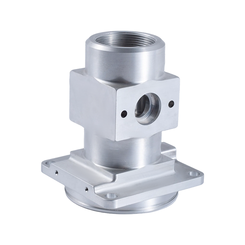
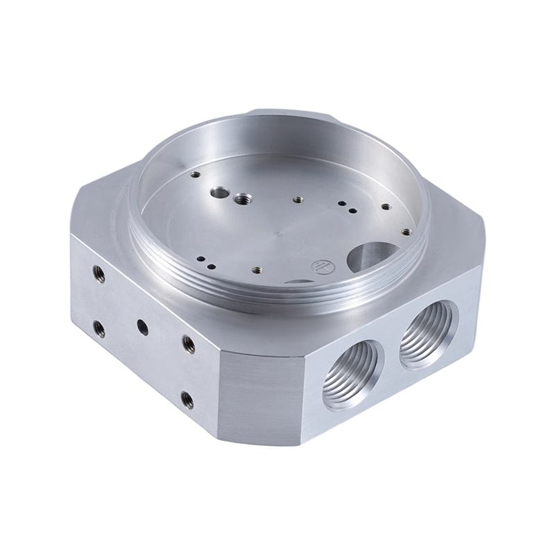
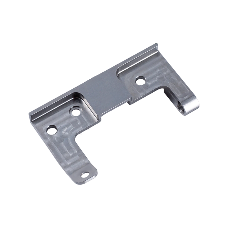


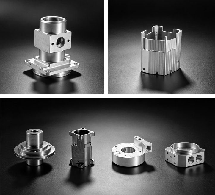
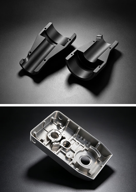
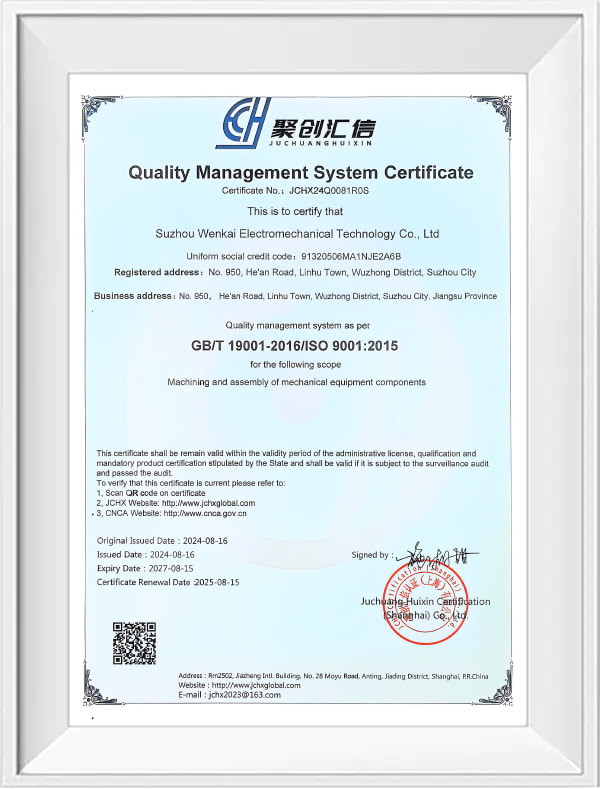
Suzhou Miaocheng Precision Machinery Co., Ltd. is a custom Transmission Gear Components manufacturer and OEM machining supplier from Wuzhong District, Suzhou, China. We machine transmission-related components in our ISO 9001:2015 certified plant using 3-axis, 4-axis and 5-axis CNC milling centers, supported by precision grinding and CMM inspection. This category covers the parts that position, house or drive gear sets—housings, carriers, flanges, gear blanks, shift elements and mounting structures—produced from customer drawings, 3D models or physical samples.
What We Supply in This Category
Transmissions, gearboxes and drive modules typically contain several milled components that support gear sets, locate bearings or carry shift loads. The common requirement across all of them is dimensional consistency: bores must hold gear positions, mounting faces must stay parallel, and dowel or bolt patterns must repeat exactly from part to part.
| Component Form | Typical Machined Features | Primary Concern |
|---|---|---|
| Gear housings and casings | Precision bores, dowel holes, gasket faces, oil galleries, counterbores | Bore position and parallelism directly affect gear mesh and bearing life |
| Carriers and shift forks | Contoured arms, machined slots, drilled holes, cam-like surfaces | Positional accuracy and thin-wall stability determine shift quality |
| Gear blanks and flanges | Face milling, bolt circles, keyways, pilot bores, hub steps | Locating features must stay concentric and parallel for downstream operations |
| Mounting plates and brackets | Milled faces, threaded holes, lightening pockets, deburred edges | Flatness and hole tolerance influence modular assembly and repeatability |
Multi-Axis CNC Milling for Transmission Components
Our machining range is built around dozens of high-precision 3-axis, 4-axis and 5-axis CNC machining centers. For transmission components, multi-axis machining brings two practical advantages: fewer set-ups and better positional accuracy. A housing that requires bores on several faces—or a carrier whose slot and hole pattern must stay true to a common datum—can be machined in one clamping, reducing datum shift and shortening handling time.
Many transmission parts also have thin-wall sections and tight internal geometry. Machining these reliably requires the right toolpath strategy and fixturing that holds the part without deflection. We plan the machining sequence around the component's weakest sections and use finishing strategies that keep dimensional stability predictable.
Where the component also includes cylindrical or ground features—such as a gear shaft, bushing surface or bearing journal—we combine the milling route with our CNC Turning Parts line and precision grinding machines, allowing full-process manufacturing from roughing to finishing within one facility.
Materials and Critical Specifications
The material grade on the drawing determines cutting tools, speeds, fixturing and the heat-treatment sequence. Transmission components are commonly specified in aluminum alloys for lightweight housings and electric drive units, alloy steel or stainless steel for gears, shafts and structural parts, and engineering plastics for development prototypes. We machine the grade called out in the specification and flag any machinability considerations during the RFQ review.
From a tolerance standpoint, the critical characteristics in this category are the ones that control gear engagement and bearing seating: bore diameters, bore-to-bore center distance, face perpendicularity, parallelism of machined datums and positional tolerance of dowel and mounting holes. Surface finish on sealing faces, bearing seats and sliding surfaces affects function as well. We review these features before quoting so the process plan targets the characteristics that actually matter in service.
Quality Assurance and Inspection
Transmission components are safety- and performance-relevant, so inspection cannot be treated as an afterthought. Our quality system is certified to ISO 9001:2015, and we maintain a full-process inspection system with 3 CMMs, precision height gauges and vision measuring machines. Incoming material verification, in-process dimension checks and final outgoing inspection are applied to every production route.
CMM inspection is especially valuable for this category because it verifies bore center distances, true position callouts and complex datum structures that a caliper or micrometer cannot adequately confirm. We can structure the inspection report to follow the GD&T scheme on your drawing and supply measurement data for the characteristics you nominate as critical. Burr condition, edge quality and internal cleanliness are also treated as production requirements, since loose burrs or inconsistent break-edge control can compromise a gearbox during operation.
Prototype, Small-Batch and Module Assembly Support
Not every transmission project begins as a full production order. We support single-piece prototypes, development batches and low-volume production through our Small-Batch Prototype Machining service, and we also produce components directly from customer drawings or samples via Custom Machining from Drawings/Samples. Early engagement with our engineering team helps identify fixturing, tool-access or tolerance-stacking issues before production begins.
We also provide module assembly. For transmission-related products, this can mean combining machined parts with purchased hardware, aligning datums and performing pre-shipment function checks. That reduces the number of interfaces the customer must manage and gives a single accountable partner for the supplied assembly.
Information We Use to Prepare Your Proposal
To prepare an accurate quotation and machining plan, our engineering team uses the following project inputs:
- 2D drawing (PDF/DWG) with GD&T, or 3D model (STEP/IGES) plus critical tolerance callouts
- Material grade, heat-treatment state and hardness requirements
- Critical features: bores, gear locating datums, keyways, splines, threads, sealing faces
- Surface finish and edge-condition requirements
- Quantities: prototype, low-volume or annual production figures
- Secondary operations: grinding, surface treatment, marking, assembly or special packaging
- Target schedule and delivery destination
If the drawing is still evolving, we can quote from a preliminary concept and update the plan once the design locks. The earlier we review the part, the easier it is to resolve manufacturability questions before tooling is committed.
Frequently Asked Questions
Can you produce transmission gear components from a physical sample rather than a drawing?
Yes. We measure the sample, build the machining plan around its critical features and confirm the interpretation with you before cutting metal. Key characteristics can be verified by CMM and documented in a dimensional report.
Does the factory perform gear cutting such as hobbing or shaping?
Our standard scope covers the milled and ground features of transmission components—housings, carriers, flanges, blank preparation and locating features. If a part requires gear-tooth generation, we discuss the process route with you and confirm which operations remain inside or outside our direct machining scope for that project.
How do you ensure bore positions and datum relationships stay consistent across a batch?
We combine controlled clamping strategies, in-process measurement and final CMM inspection. Features that require tight true-position tolerance are called out in the control plan and monitored during machining so drift is detected before a full batch is completed.
Can you supply prototypes first and then scale to higher volumes?
Yes. We regularly start with small-batch prototype machining, qualify the process and then transition to larger production quantities. The same inspection rigor applies at both stages, and lessons from the prototype stage are incorporated into the production work instruction.
What documentation do you provide with each delivery?
Our standard package can include CMM reports, dimensional inspection records, material traceability documents and, where contractually agreed, process instructions and assembly records. The exact documentation set is confirmed during the quotation stage.



