English
A 0.006 mm runout on a 12 mm stainless motor shaft never appears on a drawing review, yet it decides whether a spindle housing runs quiet at 6,000 rpm or shakes a bearing loose inside eight months. High precision industrial CNC machined parts are judged by the tolerance band and the inspection record behind it, not by how complicated the geometry looks.
Buyers who treat precision as a marketing adjective pay for it twice: once on the quotation, and again when the first article arrives with an inspection report that proves nothing about the features that actually matter. The useful definition is narrower, and it is hard to fake.
Cost multipliers in this article are planning indices for process comparison, not quotations or price commitments.
Content
- 1 What Actually Makes a CNC Part High Precision
- 2 Tolerances and Surface Finish Have to Be Specified Together
- 3 Material and Heat Treatment Rewrite the Machining Plan
- 4 Six Application Patterns That Set the Real Requirements
- 5 How Tolerance Converts Into Cost
- 6 Verifying a Supplier Before You Release the Drawing
- 7 Module Assembly and the Company Behind the Parts
- 8 Questions Buyers Ask Before Releasing a Drawing
What Actually Makes a CNC Part High Precision
High precision industrial CNC machined parts hold 0.020 mm or tighter on critical features, and 0.005 mm is achievable on turned diameters below 50 mm when machine rigidity, thermal control and the measurement loop are all built for that band.
Three things separate a precision shop from a general machine shop, and none of them is the spindle speed printed on the brochure. Thermal stability of the work envelope comes first: a 1 deg C drift across a 500 mm aluminium component moves roughly 12 micron, which consumes an entire 0.010 mm band before a tool touches metal. Fixturing comes second, because clamping force distorts thin walls and bushings by more than the tolerance they are supposed to hold. The third is in-process gauging, since parts measured only at final inspection are already scrap by the time the drift is discovered.
| Tolerance band | Typical feature | Verification method | Common failure mode |
| 0.100 mm | Brackets, covers, clearance holes | Caliper on first article | Stack-up drift across a multi-part assembly |
| 0.050 mm | Housing bores, plate flatness | Micrometer and height gauge | Ovality introduced by clamping |
| 0.020 mm | Shaft journals, spigot diameters | Bore gauge plus CMM sampling | Thermal growth during long cycles |
| 0.010 mm | Valve cores, gear bores, sensor housings | CMM with roundness check | Tool wear between offset corrections |
| 0.005 mm | Spindle shafts, hydraulic spool lands, surgical components | CMM plus cylindricity and roundness | Fixture-induced distortion after release |
Tolerances and Surface Finish Have to Be Specified Together
A diameter tolerance without a roundness and finish callout is an incomplete specification: a 0.010 mm bore machined at Ra 3.2 micron will leak where the same bore at Ra 0.8 micron seals, because the leak path is the surface, not the diameter.
The callouts that carry the most weight in production are predictable, and they are the ones drawing reviews skip most often.
- Position and profile of datum-referenced hole patterns, because a 0.05 mm positional error on a four-hole flange becomes a 0.1 mm bolt-up fight on the assembly line.
- Cylindricity and total runout on rotating parts, since a diameter measurement never describes a shaft that has to spin at 12,000 rpm.
- Surface finish on sealing faces, hydraulic spools and bearing seats, where Ra 0.4 to 0.8 micron is the practical range for a ground or fine-turned face.
- Edge break and burr limits, because a 0.2 mm burr inside a fluid passage fails a functional test the CMM will never detect.
- Material condition modifiers, which decide whether a hole is accepted at its maximum or minimum size.
Where a drawing stays silent, the shop falls back on general tolerances, and general tolerances are chosen for cost rather than function. That is why a part can pass inspection and still fail assembly. Turning-specific limits, including how tool nose radius and feed rate convert into achievable roundness, are covered in this guide to CNC turning tolerances and materials.
Material and Heat Treatment Rewrite the Machining Plan
The same geometry in 304 stainless steel, 17-4PH, 6061-T6 aluminium and Ti-6Al-4V needs four different process routes, and each route lands on a different achievable tolerance even on identical equipment.
- Aluminium 6061-T6 expands about 23.6 x 10^-6 per K, roughly double carbon steel at 11.7 x 10^-6 per K, so a warm shop that holds steel will drift out of band on aluminium.
- 304 stainless work-hardens at the cut, which raises tool pressure and turns thin-wall bushings and sleeves into a fixturing problem before it ever becomes a dimensional one.
- 17-4PH in the H900 condition reaches roughly 44 HRC and is normally machined before aging; the 0.0004 to 0.0006 in/in contraction during aging has to be planned into the stock allowance.
- Ti-6Al-4V conducts heat poorly, so the heat stays in the tool edge, tool life drops, and an operator compensating with higher feed rates trades tolerance for throughput.
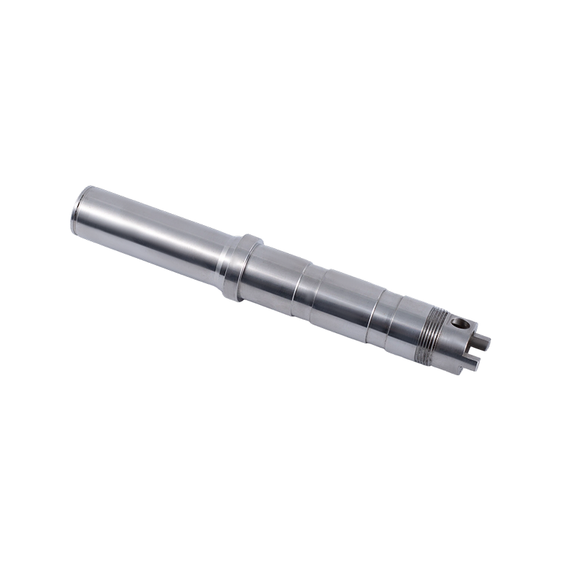
Shafts show the pattern clearly. A stainless motor shaft with a 0.005 mm journal tolerance and a 0.8 micron finish is not a turning job with a tight number attached; it is a sequence of rough turn, stress relief, finish turn and, in most cases, grind.
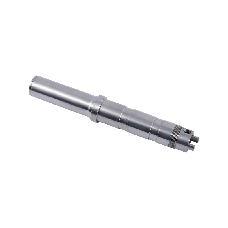 Precision Stainless Steel Motor Shaft for Motor ApplicationsCustom stainless motor shaft machined with combined turning and grinding for ±0.005 mm accuracy and consistent concentricity in demanding motor applications.View Product →
Six Application Patterns That Set the Real Requirements
Application decides which single requirement dominates a drawing, and that requirement is rarely the one printed largest in the title block.
| Sector | Typical machined part | Governing requirement |
| New energy vehicles | Precision small chassis components | Fatigue life and coating adhesion under vibration |
| Medical devices | Minimally invasive surgical instrument components | Ra 0.4 finish plus passivation and burr-free edges |
| Aerospace | Lightweight alloy structural components | Mass control with full material traceability |
| 5G communications | RF cavities and filter housings | Channel-to-channel dimensional consistency |
| Automation equipment | Inspection and positioning tooling base plates | Flatness and hole position across the full plate |
| Hydraulic and pneumatic | Valve cores, seats and control bodies | Fit clearance held in the 0.003 to 0.008 mm range |
Fluid control is the least forgiving of the six. A spool land that runs 0.004 mm loose leaks internally, and one that runs 0.002 mm tight seizes when the oil reaches operating temperature, so the tolerance window is a functional limit rather than a drawing preference.
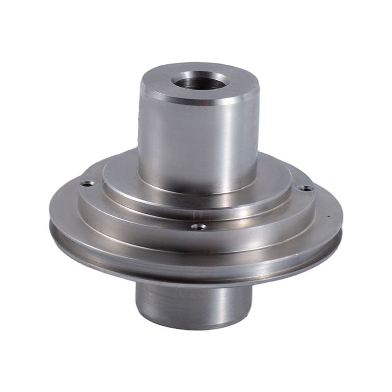 Precision Hydraulic Valve Core for Fluid ControlCustom-turned hydraulic valve core with grinding for roundness and surface finish, plus hardening for wear resistance in fluid-control valve systems.View Product →
How Tolerance Converts Into Cost
Tightening one critical feature from +/-0.050 mm to +/-0.005 mm typically multiplies machining and inspection effort by 3 to 4.5 times, because the work shifts from cutting metal to proving it.
Four cost lines move first when a band tightens: fixturing, in-process gauging, cycle time from lighter finishing passes, and scrap rate during ramp-up. A quote built only from cycle time will be wrong by the second batch.
The practical move is to specify tight tolerances only on features that touch something else. A housing with eight holes rarely needs eight precision holes; it needs two locating features at 0.010 mm and six clearance holes at 0.2 mm, and that distinction is visible on the invoice.
Verifying a Supplier Before You Release the Drawing
A supplier is verified by documents you can audit, not by sample parts that were hand-picked for the visit.
- First article report mapping every GD&T callout to a measured value
- CMM output stating the measurement uncertainty of the program
- Material certificates with heat numbers traceable to the lot
- Process route naming heat treatment and surface finish subcontractors
- A single pass or fail sheet with no numeric results
- Caliper readings offered as proof on a 0.010 mm callout
- Material grade stated on the drawing but absent from any certificate
- No record of which operation produced the critical feature
Ask for the process route before the price. A supplier who can name the operation, the machine and the gauge for each critical feature in under five minutes is describing a process they run. A supplier who answers with equipment photographs is describing a brochure.
Module Assembly and the Company Behind the Parts
Suzhou Miaocheng Precision Machinery Co., Ltd. was established in October 2012 in Wuzhong District, Suzhou, and relocated to its current site at 950 He'an Road, Linhu Town, in March 2017. The company combines precision part machining with module assembly across CNC turning, CNC milling, custom machining and industry-specific components for new energy vehicles, medical devices, aerospace, 5G electronics, automation equipment and hydraulic-pneumatic systems.
Module assembly is where precision stops being a drawing attribute and becomes an interface problem. Two parts that each pass inspection at 0.010 mm can still stack to 0.025 mm at a bolted joint, so the assembly drawings and the part drawings have to be tolerance-analyzed together rather than signed off separately. Buyers with drawings, samples or a partially built assembly can route the request through custom machining from drawings and samples, which keeps the quoting step tied to a real geometry file instead of a description.
Questions Buyers Ask Before Releasing a Drawing
What tolerance should a non-critical feature carry?
Use 0.2 mm on clearance holes and non-mating surfaces, and spend the budget on faces that touch something else. Relaxing a clearance hole from 0.050 mm to 0.200 mm typically removes one inspection step and one finishing pass, which recovers 10 to 15 percent of part cost without changing assembly behavior.
How many parts should a first article cover?
Three parts from the same setup, with one fully measured on a CMM and all three measured on the critical features. One sample proves the machine can hit the number once; three from a running process prove the process holds it.
Does a tighter tolerance always produce a better part?
No. Below the point where the measurement system can resolve the tolerance, extra precision adds cost without adding function. Keep a ratio of five to one or better between the tolerance and the measurement uncertainty, otherwise the number on the drawing stops carrying information.
How should two CNC quotes be compared?
Compare them line by line on process route rather than on the total. The lower quote usually differs in one of three places: fewer inspection steps, a skipped stress relief, or a lower-grade material certificate, and each of those moves the failure point downstream into your assembly line.