English
A 0.02 mm flatness callout on a 180 mm aluminum housing is not the hard part. The hard part is holding that flatness after 14 tapped holes, three intersecting bores, a 1.5 mm wall, and a 0.4 Ra finish have all been cut. High precision complex milling components fail in production for reasons that rarely appear on the drawing: tool deflection, thermal drift, weak workholding, or an inspection plan that cannot reach the critical feature.
Conclusion first: complex milling is a process-control problem, not just a machine problem. The right supplier will review geometry, tolerance stack-up, material condition, and metrology before quoting. If those four items are not part of the quote, the price is only a guess.
For a baseline on how milling parts are classified before complexity is added, see this guide to precision milling parts. It helps separate standard features from the features that drive risk.
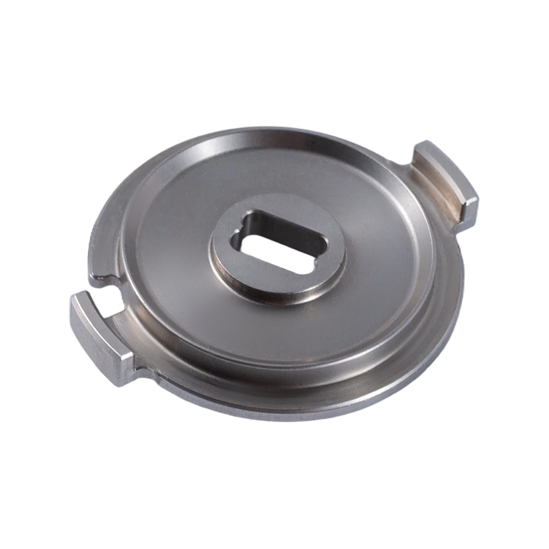
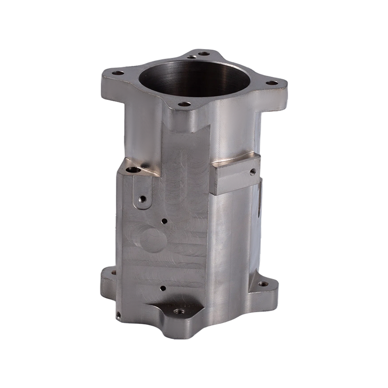
 Custom Complex Multi-Hole Prototype Milling PartsCustom multi-hole milled components for prototypes where relative hole positions, bores, cavities, and overlapping manufacturing constraints drive the machining plan.View Product →
Content
- 1 What Makes a Milling Component Complex?
- 2 Tolerances That Deserve Attention
- 3 Design Features That Create Risk
- 4 Material Choices and Their Effect on Precision
- 5 Inspection and Process Control
- 6 Selecting a Supplier for High Precision Complex Milling Components
- 7 Cost and Lead Time Levers
- 8 Bring the Drawing and the Critical Function Together
What Makes a Milling Component Complex?
A component becomes complex when several manufacturing constraints overlap. A part with a deep pocket alone may be routine. A part with a deep pocket, a cross hole breaking into the pocket, a 0.05 mm true position callout, and a hardened material is a different job. The overlap, not any single feature, is what changes the process plan.
Complex milling components usually share at least three of these conditions:
- Features that require multiple setups or 4-axis and 5-axis motion.
- Tolerances tighter than +/-0.025 mm on critical dimensions or locations.
- Thin walls, tall ribs, or unsupported sections that move under cutting force.
- Deep cavities, small corner radii, or long reach tools that deflect.
- Materials that work-harden, conduct heat poorly, or stress-relieve unpredictably.
- Inspection access that is limited by geometry or surface finish requirements.
The practical impact is simple: as complexity rises, the quote depends less on machine hourly rate and more on fixture design, tool selection, in-process checks, and rework risk. A supplier who quotes only from a PDF and a material callout is likely to discover the real cost after the first article.
| Complexity driver | Why it matters | Practical control |
|---|---|---|
| Multi-axis features | Reduces setups but increases tool reach, collision risk, and programming time. | Verify post-processor accuracy and simulate the full toolpath. |
| Thin walls or ribs | Cutting force and heat can move the part after machining. | Use light passes, support material, stress relief, and controlled clamping. |
| Tight true position | Small errors in datum setup multiply across features. | Control datums early and measure the feature in the same setup when possible. |
| Deep cavities | Long tools deflect and chip evacuation becomes unreliable. | Choose tool geometry, coolant strategy, and pecking cycles for the depth. |
| Hard or gummy materials | Tool wear, built-up edge, and thermal growth change dimensions. | Match carbide grade, coating, speed, feed, and coolant to the material lot. |
Tolerances That Deserve Attention
Not every dimension on a complex milling component deserves the same attention. A typical print may carry +/-0.1 mm on non-critical features, while two or three features carry +/-0.01 mm, a 0.02 mm flatness callout, or a 0.025 mm true position. The cost is rarely in the tolerance number alone. It is in proving that the tolerance is held across the production run.
Three tolerance questions should be answered before production:
- Which dimensions are functional, and which are only reference dimensions?
- Which datums control the tightest features, and can they be machined in one setup?
- Which measurement method will be used, and does it have the needed uncertainty ratio?
If a feature cannot be measured reliably, it cannot be controlled reliably. That is why high precision work often moves to a supplier with both multi-axis machining and disciplined metrology. When a print calls for tolerances beyond normal milling ranges, the process may need custom CNC machining with dedicated fixtures, temperature control, and first-article inspection.
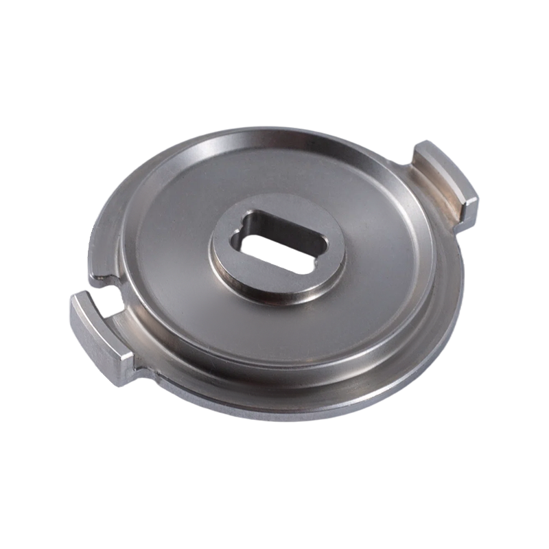
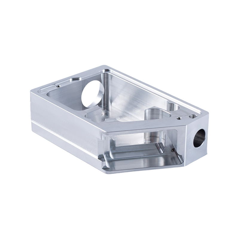
 Custom Ultra-High Precision Tolerance Machining CapabilityReview this capability category for non-standard parts needing controlled tolerance sequences, multi-axis machining, and CMM-backed inspection.View Product →
Design Features That Create Risk
Some features look harmless in CAD but create disproportionate risk in the mill. The following list is a practical DFM checklist for complex milling components:
- Sharp internal corners that force a small tool and slow feed rates.
- Threads starting within 1 mm of a wall or intersecting hole.
- Cross holes that break into a bore and create burrs that are difficult to remove.
- Pocket depths greater than three times the cutter diameter.
- Thin floors under a cavity that deflect during clamping or cutting.
- Surface finish callouts on surfaces that do not need to seal, slide, or mate.
- Undercuts or back-side features that require special tooling or extra setups.
Each item can be managed, but each one adds process steps. The best time to remove risk is before the first toolpath is posted. A supplier that returns a DFM note with specific feature-level comments is usually better prepared than one that only asks for a purchase order.
Material Choices and Their Effect on Precision
Material behavior often decides whether a complex milling component is stable or unpredictable. Aluminum 6061 machines quickly but can move after material removal if the stock is not stress-relieved. Aluminum 7075 offers higher strength but can be more sensitive to sharp tools and heat. Stainless steels such as 303, 304, and 316 resist corrosion but work-harden and conduct heat poorly, which raises cutting temperature and tool wear.
Alloy steels like 4140 hold strength and wear resistance, yet they may need pre-hardening or post-machining heat treatment that introduces distortion. Titanium combines high strength with low thermal conductivity, so heat concentrates at the cutting edge and can cause chatter or premature tool failure. Brass and copper machine well in some grades but can be gummy in others. Plastics and composites add their own risks: fuzzing, melting, fiber pull-out, and dust control.
The practical rule is to match the material specification to the functional requirement, then let the machining plan follow. If a material is chosen only because it is common, it may still create avoidable cost in a complex milling component.
Inspection and Process Control
Inspection is not a final step on complex milling components. It is part of the process plan. A coordinate measuring machine can verify final geometry, but it cannot fix a datum that was machined incorrectly in setup one. In-process probing, tool-setting checks, and first-article inspection reduce the chance that a full batch is produced before a trend is noticed.
For tight-tolerance features, the measurement method should be chosen with the same care as the cutting method. A CMM with a long stylus may not reach a deep cavity accurately. An optical system may struggle with a rough surface. A hand tool may not have the resolution or repeatability for a 0.01 mm callout. When the measurement uncertainty is too close to the tolerance, the result is a debate rather than a decision.
Good process control also includes documentation: material certificates, setup sheets, tool lists, inspection reports, and traceability for critical features. These records protect both the buyer and the machinist when a question arises later.
Selecting a Supplier for High Precision Complex Milling Components
Choose a supplier by process planning and inspection discipline, not by a machine list alone. A 5-axis mill is valuable, but it cannot compensate for weak workholding, poor tool selection, or an unclear datum strategy. The stronger supplier will ask about function, volume, critical dimensions, and measurement method before quoting.
Use these criteria when comparing quotes for complex milling components:
- Does the supplier provide feature-level DFM feedback?
- Can they machine the part in the required number of setups without losing datum control?
- Do they have a defined first-article and in-process inspection plan?
- Can they document material traceability and heat treatment if required?
- Do they describe how they will handle thin walls, deep pockets, or tight true position?
- Is the lead time realistic for the inspection load, not just the machining time?
Experienced suppliers often separate prototype validation from production. The prototype proves the process, the fixture, and the inspection method. Production then follows a controlled plan instead of repeating the learning curve. For parts with multiple cavities, intersecting holes, or high feature density, that separation is often the difference between a smooth launch and a costly rework cycle.
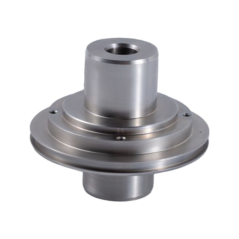
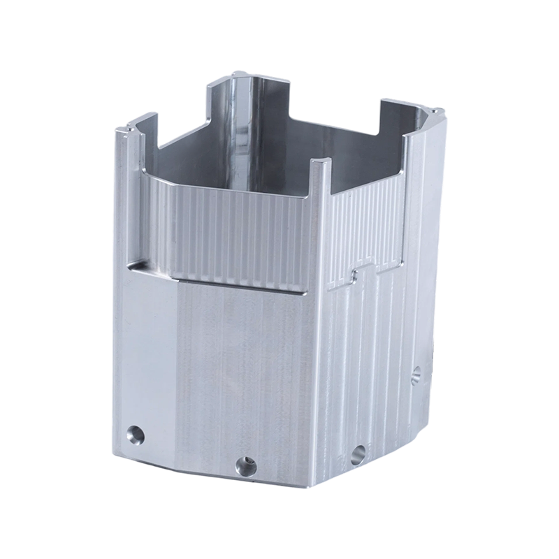
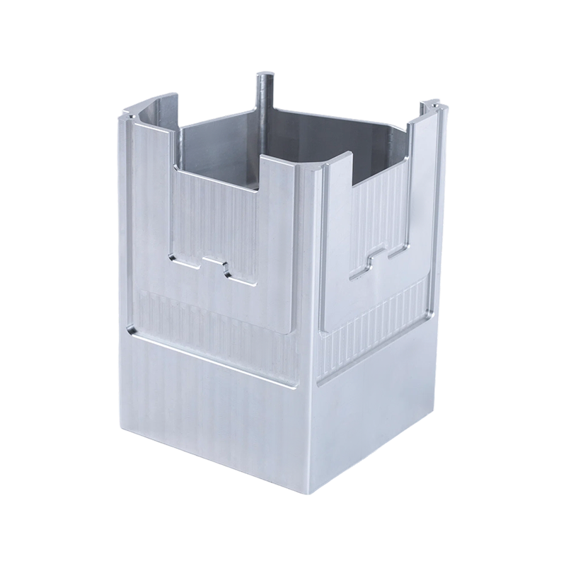 Custom Integrated Multi-Cavity Structural ComponentConsider for consolidating several cavities into one milled part, while planning for tool access and relative cavity positioning that affect downstream module mating.View Product →
Cost and Lead Time Levers
Complex milling components rarely become cheaper by asking for a discount. They become cheaper by removing unnecessary process steps. The following changes often reduce cost without harming function:
- Relax tolerances on non-functional features and mark them clearly on the drawing.
- Standardize corner radii to match available cutter sizes.
- Avoid surface finish callouts that are not required for sealing, wear, or appearance.
- Allow stock sizes that reduce material removal and setup time.
- Group features so they can be machined from fewer directions.
- Share prototype and production volumes early to support better tooling decisions.
Lead time is usually driven by the slowest inspection step, the longest lead material, or the most difficult fixture, not by the spindle. A quote that lists only machining hours is incomplete for a high precision complex milling component.
Bring the Drawing and the Critical Function Together
High precision complex milling components are successful when geometry, tolerance, material, and inspection are planned as one system. The drawing defines the target, but the process plan decides whether that target is repeatable. Start with a DFM review that identifies the few features driving risk, then build the fixture, toolpath, and measurement plan around them.
If a part has multiple setups, thin walls, tight true position, or difficult inspection access, treat those as the real specification. The rest of the drawing matters, but those features will determine cost, lead time, and whether the first article is approved without a long correction loop.