English
Thirty-two holes, one datum callout, and a first-article report that comes back red on four positions. That is the usual shape of a multi-hole structural component problem, and it rarely comes from the drill or the spindle. It comes from how the hole pattern was defined, how the part was held, and the order in which material was removed.
The short version: on OEM multi-hole structural components, the parts that pass first-article inspection and keep passing across a production year are the ones where the datum scheme matches how the part actually bolts up, hole-to-hole relationships are controlled as a group rather than as separate coordinates, and the hole finishing happens late in the sequence on a single, locked setup. Spindle speed and cutter brand matter far less than those three decisions.
The sections below explain what puts a part in this category, where tolerance stacks and clamping forces turn into scrap, and which details on a drawing or purchase order decide whether a quoted price and lead time are realistic.
Content
- 1 What Counts as an OEM Multi-Hole Structural Component
- 2 Where Hole Patterns Fail First-Article Inspection
- 3 Datums, Fixturing, and the Questions Worth Settling Before Cutting Metal
- 4 Material Choice and Machining Sequence
- 5 Cost Drivers on Multi-Hole Work
- 6 Inspection and Process Control That Catch Scrap Early
- 7 Supplier Qualification Questions for Multi-Hole Structural Work
What Counts as an OEM Multi-Hole Structural Component
These are machined parts where several accurately positioned holes carry the function, bolting, alignment, connector pass-through, fluid routing or weight reduction, while the part itself also takes load or locates other components. A flat plate with two clearance holes is not in this category. A 300 mm aluminium connector plate with 48 holes held to a positional tolerance of 0.2 mm, a 12 mm thickness and a flatness limit of 0.1 mm is.
The family usually includes:
- Multi-hole connector and interface plates that join two subassemblies.
- Mounting bases and high-rigidity brackets with mixed hole sizes for dowels, bolts and cable pass-through.
- Housings with feedthrough holes, sensor ports and mounting flanges.
- Integrated multi-cavity blocks where intersecting bores and cross-holes must line up with a mating manifold.
- Weight-relieved structural plates used in aerospace, automation and electric-vehicle chassis applications.
What separates OEM work from one-off machining is repeatability. The drawing is controlled, the same part number returns every quarter, and positions have to land in the same place across dozens or thousands of pieces, including the pieces made after a fixture is rebuilt or a tool is replaced. That is why the productive conversations start with datums, fixtures and inspection method, not with which machine will run the job.
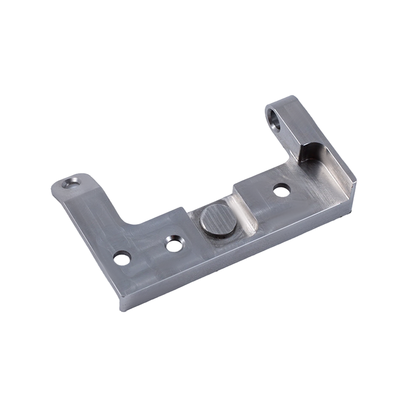
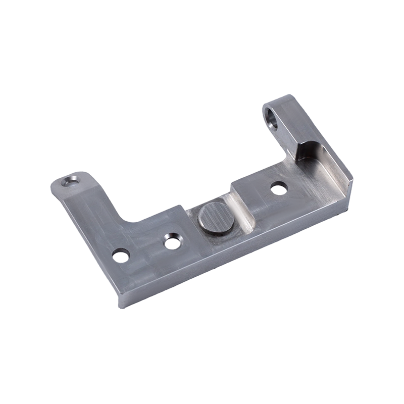 Multi-Hole Structural Connector Plate for Precision CNC MachiningWorth reviewing for multi-hole structural connections where hole position and plate flatness affect assembly stress and long-term joint reliability.View Product →
Where Hole Patterns Fail First-Article Inspection
Four causes account for most of the red marks on a multi-hole first-article report.
Coordinate tolerances that stack
Nine holes each toleranced at plus or minus 0.1 mm from the same datum edge looks harmless on paper. In practice the errors do not cancel. The hole at the far end of the pattern absorbs tool-position error, thermal drift across the plate and any re-clamping error between setups. On a 400 mm 6061 aluminium plate, a 3 degree Celsius change in shop temperature moves the material roughly 0.1 mm, which is the entire allowance before a single chip is cut.
Datums that do not match the function
If the drawing datums come from a convenient edge but the part bolts down on two dowel holes, the inspection setup and the assembly setup disagree about where the part is. The CMM reports a conforming part that will not seat on the mating fixture.
Clamping distortion on thin webs
Six-point clamping flattens a 6 mm plate with large cutouts. Holes are drilled while the part is held flat, then the plate springs back when the clamps release, and every position shifts in the same direction. Probing the part in the clamped state will not reveal it.
Sequence decisions
Holes finished before a stress-relief pass, a second face machining operation or a re-clamp lose their position. The same applies to any plan that completes a hole pattern and then removes a significant amount of material from the surrounding face.
| Callout style | What it controls | Typical failure point | Where it works well |
|---|---|---|---|
| Coordinate tolerances (plus/minus X and Y) | Each hole's location from datum edges in two axes | Errors accumulate across the pattern; a hole that passes in one axis can still miss its mating hole | Simple plates with few holes and generous clearances |
| Positional tolerance (true position) | Diameter of the zone the hole axis may occupy | Bonus tolerance at maximum material condition is claimed in the quote but never verified with functional gauging | Bolt-up interfaces and connector grids with mating hardware |
| Composite positional tolerance | Pattern location separately from hole-to-hole relationship | Misread on the shop floor when the two frames are not clearly labelled | Large plates where the pattern must mate as a unit |
| Hole-to-hole pitch only | Spacing between adjacent holes | The pattern drifts as a whole; total pin-to-pin error goes unchecked | Chain-mounted components with a floating first hole |
Reading the table as a buying rule: when a part mates with a fixed, multi-pin interface, positional tolerance and functional gauging are worth the extra inspection cost. When it mates with slotted or floating hardware, coordinate tolerances are usually enough, and tightening them only raises the price.
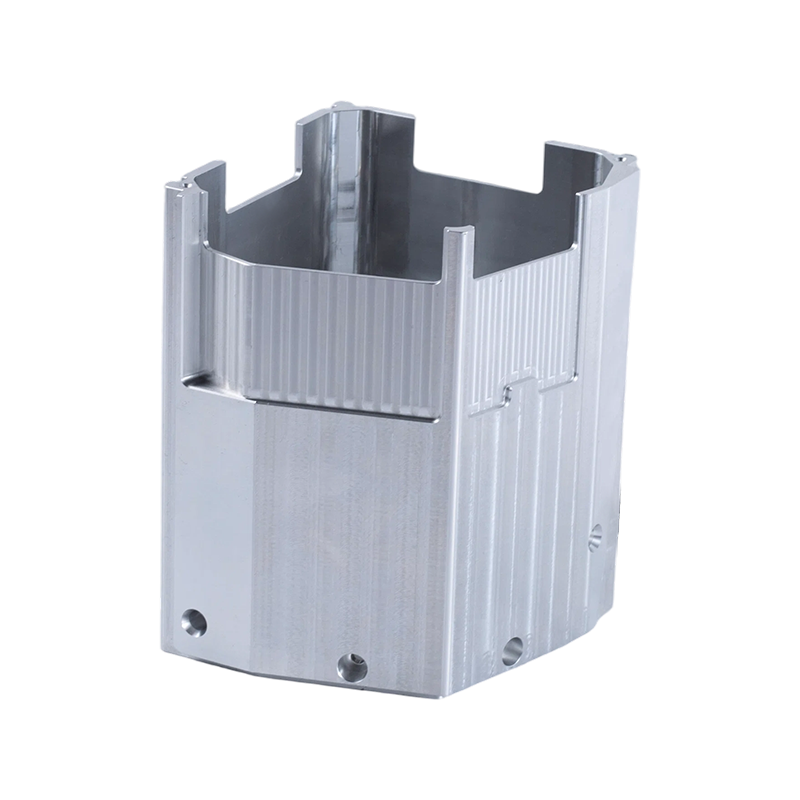
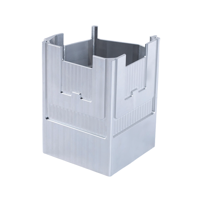 Integrated Multi-Cavity Structural Component for Custom CNC MillingA milled part combining multiple cavities to replace separate components, where cavity position and tool access affect downstream mating and machining reliability.View Product →
Datums, Fixturing, and the Questions Worth Settling Before Cutting Metal
A functional datum scheme, the one the assembly uses, normally wins, and the fixture has to reproduce it. If that is impossible because the functional datums are interrupted by pockets or holes, the surrogate datum must itself be verified against the drawing rather than assumed. Six questions resolve most of the risk in one engineering review:
- Which features locate the part in final assembly, dowel holes, a machined face, or a bore?
- Can the same datum features be held in the fixture, or does the fixture need a surrogate that must be measured first?
- Is the primary datum surface interrupted by holes, slots or pockets that prevent full face contact?
- Which holes touch mating hardware and therefore need functional gauging rather than CMM verification alone?
- What is the maximum permissible burr at each hole edge, and who confirms it at receiving?
- If the part is re-clamped for a second operation, which dimensions are deliberately moved to that setup?
An hour of engineering before the first cut settles these. Discovering them at first article costs a fixture rebuild and a week of schedule, and the drawing usually changes anyway.
Material Choice and Machining Sequence
Material affects multi-hole work in two ways: how much the part moves during and after machining, and how much the tooling suffers while making the holes.
| Material | Typical use | Movement and stability | Main risk in hole-making |
|---|---|---|---|
| 6061-T6 aluminium | Connector plates, brackets, housings | Moderate, high thermal expansion of roughly 23 micro metres per metre per degree Celsius | Built-up edge in deep holes and galling when coolant delivery is poor |
| 7075-T6 aluminium | Weight-critical brackets, aerospace plates | Higher residual stress, more distortion after heavy material removal | Warping on thin webs; needs stress relief or symmetrical removal |
| 304 and 316L stainless | Fluid and valve bodies, corrosion-exposed plates | Low expansion, work-hardens quickly | Hole-size drift, work-hardened walls and poor chip evacuation |
| 4140 alloy steel, pre-hardened | Heavy mounting bases, tooling plates | Stable once stress relieved | Tool wear across long hole patterns and heat build-up in dry cutting |
| Titanium Ti-6Al-4V | Aerospace structural parts | Low expansion, high cost of a scrapped part | Low thermal conductivity concentrates heat at the cutting edge |
| Glass-filled PEEK and PPS | Sensor housings, insulating plates | Low cutting force, high sensitivity to clamping pressure | Exit burrs and clamp marks that fail cosmetic inspection |
Sequencing matters more than material on parts with a large hole count. A workable default is rough the profile, allow the part to stabilise or stress relieve, semi-finish the faces, then drill, interpolate or ream the full pattern in one datum-locked setup without a re-clamp. Splitting a pattern across two setups doubles the stack of errors. Dowel holes with an H7 fit should be reamed or fine-bored rather than milled, and holes deeper than four times their diameter need peck cycles or through-tool coolant so chip packing does not push the drill off line.
Cost Drivers on Multi-Hole Work
On a part with 40 holes, machining time is frequently less than the sum of setup, deburring and inspection time. The cost lines that matter are predictable:
- Hole count and diameter families: every unique diameter adds a tool change. A pattern using two diameter families can run at roughly half the cycle time of one using five.
- Depth-to-diameter ratio: holes beyond four times diameter require pecking or high-pressure coolant, and beyond ten times diameter may move to a dedicated deep-hole process.
- Position tolerance: tightening true position from 0.2 mm to 0.05 mm often pushes the feature from drilling to interpolation or boring, and it usually doubles inspection time.
- Burr specification: a blanket no-visible-burr note on 200 hole edges becomes a real manual or robotic deburring line item and a schedule risk.
- Volume bands: prototypes absorb programming and fixture cost while production runs amortise it. Quoting at 1, 50, 500 and 5,000 pieces shows where the break points sit.
- Geometry that allows clustering: grouped holes at standard diameters cut travel time and tool inventory without changing function.
The same reasoning applies across general milling work, which is covered in this guide to CNC milling parts applications and selection criteria. The practical takeaway is that most cost reductions on multi-hole parts come from the drawing, not from the machine shop negotiating its hourly rate.
Inspection and Process Control That Catch Scrap Early
Verify on the machine wherever a feature can be probed, and treat the CMM report as confirmation rather than as the first measurement. A pattern that is proven wrong only after the part leaves the machine is already a scrapped part.
- In-process probing against the same datum the fixture holds, checked at the first part and then at defined intervals.
- CMM programs aligned to the drawing datums, reporting actual values rather than pass or fail alone.
- Functional gauging with pins or a mating plate on holes that carry assembly function, which is the only check that reflects real fit.
- Statistical process control on the two or three characteristics that drive function, not on every dimension on the print.
- Documentation that travels with the batch: material certificates with heat lot, inspection records with measured values, and the stated burr control method.
For applications where the pattern tolerance is tight enough that these controls are not optional, the process planning is closer to precision work than to general plate machining, which is the case for 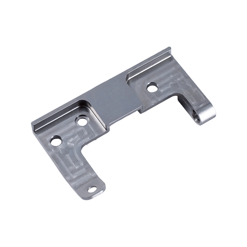 Custom Ultra-High Precision Tolerance Machining for Non-Standard ComponentsWorth reviewing for custom CNC parts where drawing tolerances, varied materials, and inspection requirements demand controlled machining sequences and repeatable batch production.View Product → programs run under drawing control.
Supplier Qualification Questions for Multi-Hole Structural Work
Before releasing a purchase order, a short technical exchange usually separates capable suppliers from responsive ones:
- Which datum scheme will be used in the fixture, and how does it map to the drawing?
- How many setups are planned, and which dimensions are held in each?
- What in-process verification is used, and at what frequency?
- How is hole position drift monitored across a long run or after a tool change?
- What is the burr control method, and how is it verified?
- Can the supplier provide first-article reports with actual values rather than pass or fail stamps?
- How are engineering changes handled once fixtures and programs exist?
Answers that come back in specific numbers, planned setups and named gauges indicate that the shop has thought about the part. Vague answers at this stage tend to reappear later as a first-article delay.
To summarise: define datums the way the part functions, control the pattern as a group instead of as isolated coordinates, finish holes late on one locked setup, and specify burr and inspection expectations in writing. Those four decisions determine fit, scrap rate and total cost on multi-hole structural components far more than any machining parameter.
Where a supplier can work from drawings or samples, hold the datum intent and the inspection plan in one conversation. Suzhou Miaocheng Precision Machinery supports this kind of work across turning, milling, custom machining and industry component programs, and the first useful step is usually a drawing review rather than a quote request.