English
A design engineer sends a sensor housing out for three units, needs them in twelve days, and marks every dimension on the drawing at plus or minus 0.01 mm "to be safe." The quote comes back at four times the expected budget and the lead time doubles. Nothing about the part was exotic; the specification was.
That pattern sits behind most prototype CNC milling parts. Cost and schedule are decided before the spindle turns, in how tolerances, material, stock, and quantity are written down. Get three things right and milling stays predictable: tolerance only what functions, pick a material that machines as easily as the test allows, and keep the geometry within reach of a standard cutter.
Content
Where Prototype CNC Milling Fits, and Where It Does Not
Milling cuts prismatic parts from solid bar or plate: pockets, ribs, slots, stepped faces, threaded holes, and bores at angles. If a prototype is largely rotational — a shaft, a bushing, a valve seat — turning is usually faster and cheaper per piece, because the blank spins instead of the tool orbiting it. Real assemblies often need both processes, and prototypes are no exception.
Against 3D printing, milling gives isotropic material, real alloy grades, and tolerances roughly an order of magnitude tighter, which matters when the part has to survive a pressure test, a press fit, or a thermal cycle. Against injection molding, it needs no tool steel, so a five-piece run is viable. The trade-off is unit cost at volume and material waste: every pocket you cut becomes chips.
| Route | Typical achievable tolerance | Tooling cost | Best suited to |
|---|---|---|---|
| 3-axis CNC milling | ±0.05 mm; ±0.025 mm on well-fixtured features | Fixtures only | Plates, brackets, housings with open faces |
| 4-axis and 5-axis CNC milling | ±0.02 mm with in-process probing | Fixtures only | Angled ports, multi-face cavities, multihole blocks |
| CNC turning | ±0.025 mm on diameters | Collets and soft jaws | Shafts, bushings, threaded connectors |
| Resin 3D printing | ±0.1 mm | None | Form and fit checks with no load |
Tolerance Is the Largest Cost Lever on the Drawing
Every dimension marked tightly buys inspection time, slower cutting parameters, and often an extra setup. Reducing a drawing from twenty toleranced dimensions to four functional ones usually saves more money than switching suppliers, and it does not compromise the test the prototype is meant to pass.
Tolerance the interfaces, not the silhouette
Bearing bores, dowel holes, seal grooves, mating faces, and connector footprints are functional. The outer envelope and non-mating edges rarely are. Put the functional dimensions under a clear tolerance block, let everything else fall at ±0.1 mm or ±0.2 mm, and the shop can machine the profile at full speed.
One tight feature is not the same as a tight part
A shop can hold ±0.01 mm on a single bore. Holding that value across a 200 mm part, in three setups and two fixtures, is a different job: it calls for temperature control, CMM verification, and possibly in-process probing. If you write a position tolerance, the datum reference frame has to be measurable — stacked plus/minus dimensions across a hole pattern often cannot be inspected at all.
Materials, Stock, and Geometry Limits
- Aluminum 6061-T6 is the default for housings and brackets: free-machining, anodize-friendly, and widely stocked.
- Aluminum 7075-T6 adds strength for structural and aerospace prototypes, at the cost of a slightly less forgiving finish.
- Stainless 303 machines freely and resists corrosion; 304 and 316 run slower; 17-4 PH adds strength after heat treatment.
- Engineering plastics such as POM, PC, ABS, and PEEK cut quickly and never rust, but check thermal expansion before trusting a tight fit.
- Brass and copper alloys are chosen for conductivity and RF behavior rather than for strength.
Stock form drives lead time more than most buyers expect. Choose plate thickness close to the finished height so the shop is not turning 80 percent of a block into chips, and confirm the exact temper is available before you promise a date. Thin walls and deep pockets set the practical limits: keep unsupported aluminum walls around 1 mm or thicker, add ribs to tall walls, and expect pockets deeper than four times the cutter diameter to need long-reach tooling and lighter passes.
Prototype Milling Parts That Come Up Most
Housings and enclosures
Sensor and instrument housings combine a controlled bore, a sealing groove, and wall thickness you can tap. On a prototype, the sealing groove and bore concentricity belong in the tight group; cosmetic radii do not.
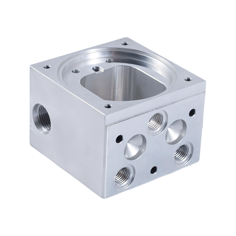 Precision Sensor Housing for Custom OEM CNC MillingCNC-milled sensor housing for custom OEM enclosure projects; worth reviewing when internal positioning and sealing or shielding requirements matter.View Product →
Brackets and mounting plates
Brackets carry load through hole spacing and thickness, so hole positions relative to each other matter more than the outer profile. Chamfers and lightening cuts can wait for the production revision.
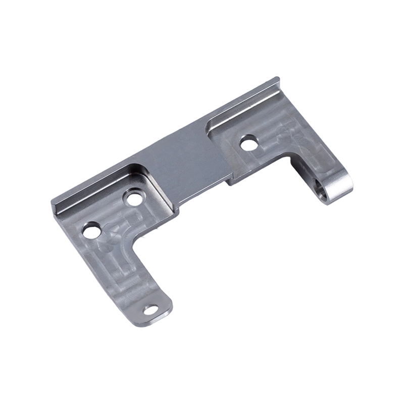 High-Rigidity CNC Milled Mounting Bracket for Automation EquipmentMounting bracket designed to fix components and absorb assembly stress; review when hole accuracy and rigidity help prevent wobble or vibration transfer.View Product →
Tooling and fixture plates
Base plates for inspection and positioning are usually flatness-critical with a hole grid. A flatness callout that matches how the plate will actually be clamped is far easier to hold than a blanket tolerance on every surface.
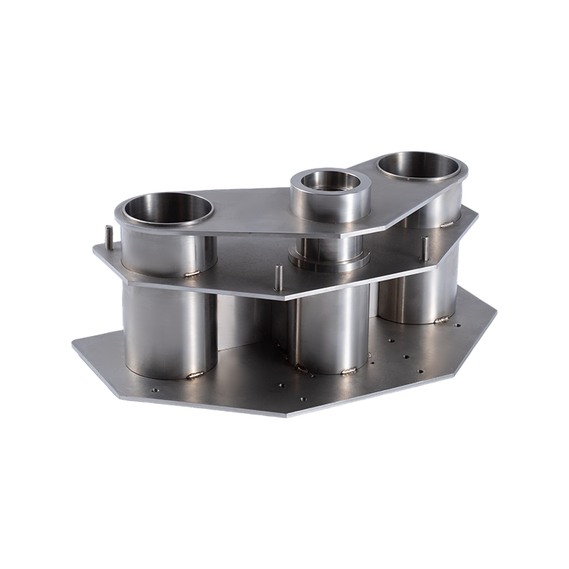 Inspection and Positioning Tooling Base Plate for Automation LinesCNC-milled reference plate for inspection or assembly; worth reviewing when flatness and locating-hole accuracy affect repeated workpiece placement.View Product →
What Actually Drives Prototype Cost and Lead Time
- Number of setups: every face that must be reached means unclamping, re-datuming, and a fresh chance for error.
- Stock removal and tool reach: deep cavities need long, thin tools, lighter passes, and more time.
- Tolerance and finish: tight limits and fine surface finishes add semi-finishing and inspection steps.
- Material hardness and availability: a specialty alloy in the wrong temper can add days before machining even starts.
- Documentation: a first article report, material certificates, and a CMM report cost money but prevent a scrap build.
- Quantity: at one to five pieces setup dominates the price; by fifty pieces, cycle time does.
Ask for a quantity ladder — three, ten, and fifty pieces — before approving the order. It shows whether you are paying for setup or for machining, and it tells you whether small-batch prototype machining can carry the design into bridge production instead of stopping at validation.
What to Send, and What to Check Before Release
- A STEP file plus a 2D drawing with a tolerance block, datums, and any GD&T callouts.
- A material specification with temper and heat treatment, not simply "aluminum."
- A short list of critical-to-function dimensions, so quoting focuses on what matters.
- Finishing requirements and their dimensional effects; hard anodize builds thickness and changes fits.
- Deadline and budget flexibility stated separately, since a longer lead time sometimes removes a weekend setup.
On the shop side, ask three questions: is the milling done in-house, who verifies the critical dimensions, and what happens if a feature measures out of tolerance — rework, remachine, or a phone call? Knowing the basics of precision milling parts lets you read a first article report instead of just accepting it. A supplier who can explain why a tolerance was relaxed is usually a better partner than one who quotes everything without comment.
Prototype CNC milling parts are a specification exercise before they are a machining exercise. Tolerance the interfaces, choose the material the test actually requires, keep walls and pockets within tooling reach, and ask for a quantity ladder. Do that and the second revision costs less than the first, which is the entire point of building a prototype.