English
 A rotary indexing table begins to vibrate at 2,400 revolutions per minute, three weeks after installation. The service technician measures the drive shaft and finds a runout of 0.03 mm against a drawing specification of 0.008 mm. Replacing the shaft solves the problem, but the downtime costs more than the part itself. Scenes like this play out across automation lines, medical device production, and aerospace assembly, and they point to a simple conclusion: precision shaft parts are mission-critical components, not commodity hardware.
The quality of a precision shaft is determined before it is turned, ground, and measured. Material choice, tolerance specification, surface finish, and the manufacturing partner's process capability all decide how long the part will hold up under load. This guide explains what precision shaft parts are, which materials and processes deliver reliable performance, and how to evaluate a machining partner who can actually hold the tolerances on your drawing.
Content
What Are Precision Shaft Parts?
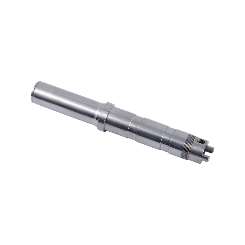
A precision shaft is a rotating component manufactured to close dimensional tolerances, usually within a few hundredths of a millimetre, and to a controlled surface finish. Precision shaft parts include solid shafts, hollow tubes, stepped profiles, splined shafts, threaded ends, and tapered sections. They transmit torque from motors to driven components, support rotating assemblies, maintain axial alignment, and, in fluid systems, act as valve stems or pump shafts.
The design of a shaft follows its duty. Choosing the correct configuration from the start avoids costly revisions later:
- Solid shafts — direct torque transmission with high bending stiffness in the smallest possible envelope.
- Stepped shafts — locate bearings, gears, and seals precisely along the axis of rotation.
- Hollow shafts — reduce weight while retaining torsional strength, common in servo and spindle drives.
- Splined shafts — transfer high torque without slippage in gearboxes and drive trains.
- Threaded shafts — provide axial adjustment or secure fastening in actuators and linkage systems.
- Tapered shafts — create self-centring, removable connections for couplings and pulleys.
Material Selection for Precision Shaft Parts
Material determines machinability, strength, corrosion resistance, and cost. The right grade prevents early failure, while the wrong one turns a precision shaft into a recurring maintenance expense. The table below summarises common shaft materials and the applications where they perform best.
| Material | Typical Applications | Key Considerations |
|---|---|---|
| Carbon steel (1045, 1215) | Automation components, hydraulic pistons, standard drive shafts | Low cost and good machinability; requires surface treatment for corrosion resistance |
| Alloy steel (4140, 4340) | Gearbox shafts, aerospace actuation, high-load transmission | High strength and fatigue resistance; needs grinding after heat treatment |
| Stainless steel (303, 304, 316) | Medical devices, food processing, marine and laboratory equipment | Corrosion resistant; 303 for machinability, 316 for demanding environments |
| Aluminium (6061, 7075) | Lightweight assemblies, prototypes, robotics links | Low density and fast machining; lower hardness reduces wear life |
| Titanium (Grade 5) | Aerospace structural shafts, surgical instruments | High strength-to-weight ratio; difficult to machine and more expensive |
| Brass (C360) | Valve stems, sensors, electrical fittings | Free-machining, non-sparking, and dimensionally stable |
How Precision Shafts Are Manufactured
CNC turning is the core process for shaft parts. A precision lathe removes material in controlled passes to hold each diameter within a few micrometres of the drawing value. For shafts with multiple steps, modern CNC turning centres machine diameters, grooves, threads, and chamfers in a single setup, which preserves concentricity from one feature to the next.
When the drawing demands extremely tight tolerances, cylindrical grinding follows turning. Ground surfaces provide better roundness, lower surface roughness, and more consistent control over diameter than turned surfaces alone. Most precision shafts also require secondary operations such as keyway milling, cross drilling, deburring, and surface treatments including black oxide, zinc plating, anodising, or nitriding.
Inspection and Metrology
Machining accuracy is only half of the story; measurement proves it. A capable supplier verifies each diameter with micrometers or air gauges, measures roundness with a dedicated roundness tester, and checks surface finish with a profilometer. Runout at bearing seats and concentricity between journals are the first characteristics to reject a shaft, so they require explicit measurement before the part leaves the shop.
Tolerance Classes and Practical Specifications
Tolerance is the practical language of a shaft drawing. Too loose, and the part vibrates or wears prematurely; too tight, and manufacturing cost rises sharply for no functional gain. The table below shows common tolerance ranges and the processes that can hold them.
| Tolerance Range | Typical Applications | Manufacturing Route |
|---|---|---|
| ±0.05 mm | Spacers, collars, general housings | CNC turning |
| ±0.02 mm | Bearing journals, seal diameters, motor shafts | CNC turning with fine finishing passes |
| ±0.005 mm | Precision spindles, servo shafts, gear seats | Turning followed by cylindrical grinding |
| Below ±0.005 mm | Aerospace mechanisms, metrology instruments | Grinding plus lapping or honing in a temperature-controlled environment |
Realistic tolerance specification is a matter of cost control. If a bearing seat requires an interference fit, the acceptable range is governed by the bearing bore tolerance, which usually lands near ±0.01 mm. Specifying grinding on every surface of a lightly loaded shaft adds unnecessary expense. A good drawing review will flag these mismatches before production rather than after.
Evaluating a Precision Shaft Manufacturer
Selecting the right machining partner matters as much as the drawing itself. A supplier that measures accurately and communicates process expectations prevents field failures, assembly delays, and expensive rework. These are the criteria that should shape the decision:
- Material certifications and heat-treatment traceability confirmed before production starts.
- In-house inspection equipment, including a coordinate measuring machine, roundness tester, and surface profilometer.
- Demonstrated experience with stepped, splined, or ultra-tight-runout shaft parts similar to your application.
- A willingness to review the drawing for manufacturability and flag tolerance risks early.
- Support for small-batch prototyping instead of requiring large order quantities.
- Clear procedures for surface treatment, cleaning, and packaging to prevent transit damage.
Custom Precision Shaft Parts from a Specialist Partner
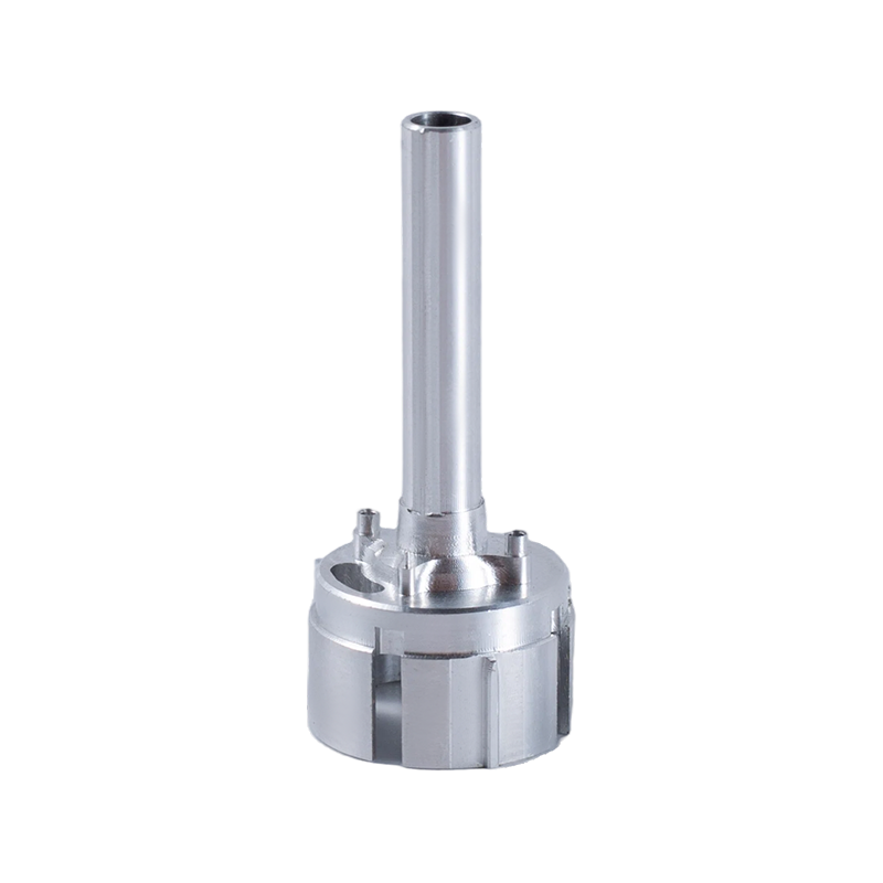
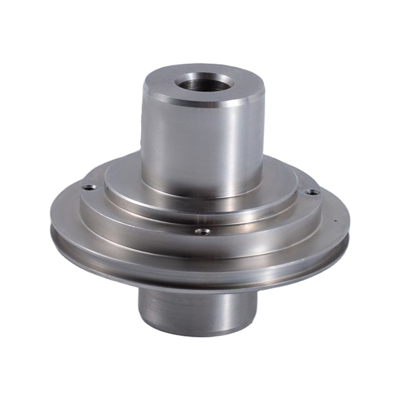
Suzhou Miao Cheng Precision Machinery Co., Ltd. has focused on precision component machining and module assembly since 2012. Precision shaft parts sit at the core of its CNC turning portfolio, which also covers bushings, sleeves, threaded joints, micro turned parts, and valve components. The company supports custom machining from drawings or samples, small-batch prototype machining, and ultra-high-precision tolerance machining for industries including new energy vehicles, medical devices, aerospace, 5G communications, automation equipment, and hydraulic and pneumatic systems.
A shaft drawing with tight runout and surface finish callouts is a routine request for a shop that serves these industries. The practical approach is to share the drawing early, agree on material grade and heat treatment, and confirm the tolerance class and inspection report format before the first piece runs. That discipline, on both sides, is what keeps precision shaft parts performing reliably in the field.