

 English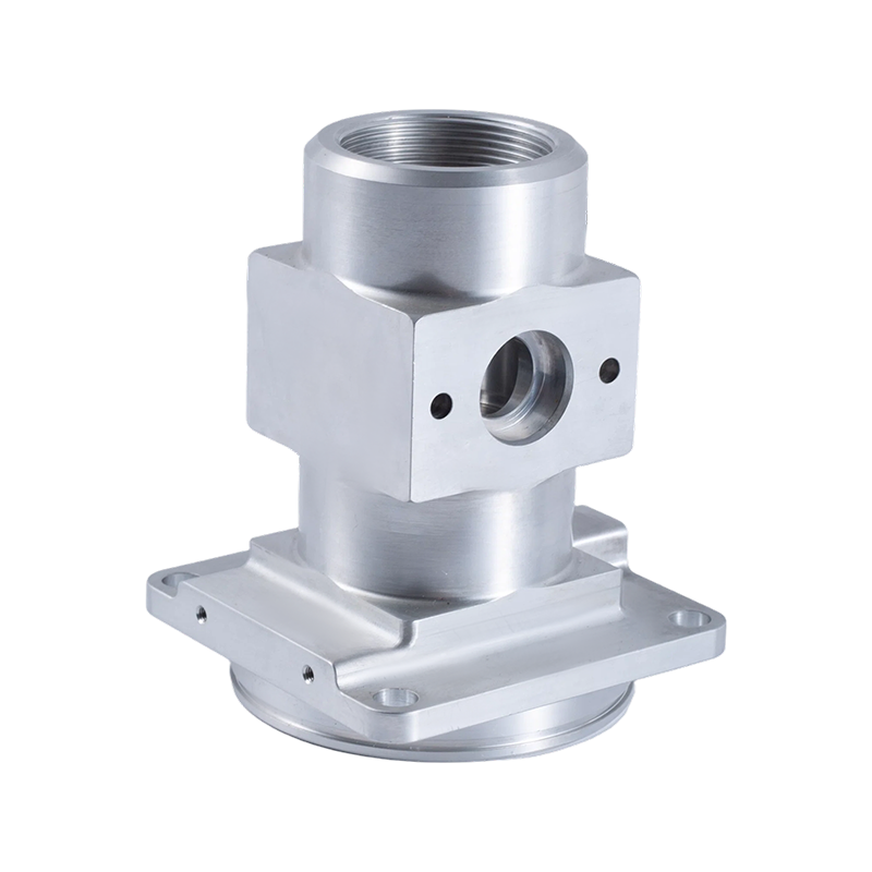


What We Supply in This Category
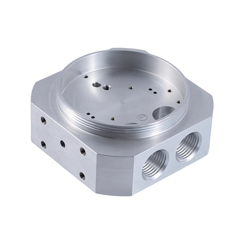
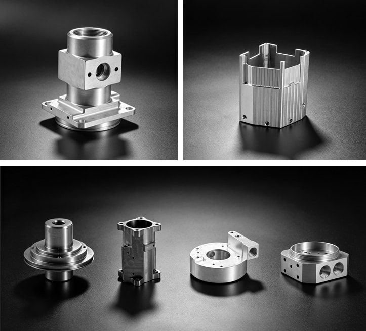
This category covers turned parts that join, connect, seal or fasten other elements of a system. Typical components include adapters, reducing fittings, couplings, unions, nipples, threaded sleeves, connector bodies, sensor housings with threaded ends, banjo fittings and precision threaded collars. The common feature is a machined thread — external, internal or both — that must meet a defined fit class and often works together with a sealing surface, O-ring groove or tapered seat.
The table below maps the main component types we supply to their typical application fit.
| Component type | Typical turned geometry | Application fit |
|---|---|---|
| Adapters & reducing fittings | External threads, hex flats, tapered or flat seats | Hydraulic and pneumatic circuits, instrumentation lines |
| Couplings & unions | Internal threads on both ends, sealing face, wrench flats | Fluid transfer, compressed air, process and utility lines |
| Connector bodies | Threaded ends, cross-drilled ports, O-ring grooves | Sensors, pneumatic and electrical connectors |
| Banjo fittings & bolts | Head with cross passages, controlled sealing face | Brake and fuel systems, lubrication circuits |
| Threaded sleeves & inserts | External/internal thread combinations, thin walls | Mounting, adjustment and threaded repair applications |
Many threaded joints also carry a fluid-control or valve function. When that is the case, we assess the part together with the Valve & Fluid Control Turned Parts category during process planning so the machining, sealing and inspection strategy matches the full function of the component.
Geometry and Application Fit
Threaded joints and connectors are fundamentally rotational parts: even when the finished component includes a hex, flange or cross-drilled port, the turning operation establishes the main axes, diameters and thread positions. That makes CNC turning the natural base process, while radial ports, flats or drive features are added with driven tooling or a subsequent milling step depending on the part design.
Part geometries that fit this category well include:
- External and internal threads on cylindrical bodies
- Hex forms, spanner flats and tube-nut profiles
- Tapered pipe-thread seats and parallel sealing seats
- O-ring grooves and seal grooves
- Cross holes, radial ports and intersecting bores
- Stepped profiles with controlled concentricity between diameters
In application terms, this category serves fluid handling, pneumatic control, instrumentation and sensor mounting, automotive air and fluid lines, medical and semiconductor equipment, and aerospace structural or fluid components. If the part's primary function is torque transmission along its axis rather than joining or sealing, the more relevant category is Precision Shaft Parts; wall-thickness-dominated cylindrical parts without a thread function sit in the bushings and sleeves family. Choosing the right starting category affects how we plan the process and which inspection criteria take priority.
Materials, Thread Standards and Critical Specifications
Material selection is driven by the service environment: operating pressure, media, temperature, corrosion resistance, weight targets and assembly method. Stainless steels are common in fluid, medical, food and marine applications; aluminum alloys suit weight-sensitive automotive, aerospace and automation assemblies; brass and copper alloys appear where conductivity, machinability or low friction matters; carbon and alloy steels are used for high-pressure industrial fittings. The material grade also influences cutting parameters and whether deburring, passivation or other finishing steps are needed.
Thread standards commonly specified in this part family include metric ISO threads (typically 6g/6H fit), UN/UNF/UNC series, BSP parallel pipe threads, and BSPT or NPT tapered pipe threads. Tapered threads seal by flank interference; parallel threads normally seal through an O-ring, bonded washer or metal-to-metal seat. Each standard has its own tolerance system, gauging rules and sealing behavior, so the drawing callout must be complete before tooling is selected.
Specifications that most affect machining feasibility, cost and sealing reliability:
- Thread class and pitch-diameter tolerance
- Concentricity between thread pitch diameter, sealing seat and hex flats
- Surface finish on sealing faces and O-ring grooves
- Deburring of thread starts and cross-hole intersections
- Cleanliness requirements for medical, semiconductor and hydraulic circuits
- Marking, passivation or material traceability requirements
Manufacturing and Quality Approach
Machining threaded joints and connectors requires control over tool path, cutting parameters and inspection method. We produce these parts on CNC turning equipment, with 3-, 4- and 5-axis machining centers available for features outside the turning axis. The threading method — single-point cutting on the lathe, tapping or thread milling — is selected during process planning from the thread size, material and batch quantity. Precision grinding machines are available for finishing operations where tight concentricity or sealing-surface quality is required, and module assembly can be included when the connector is delivered as part of a larger subassembly.
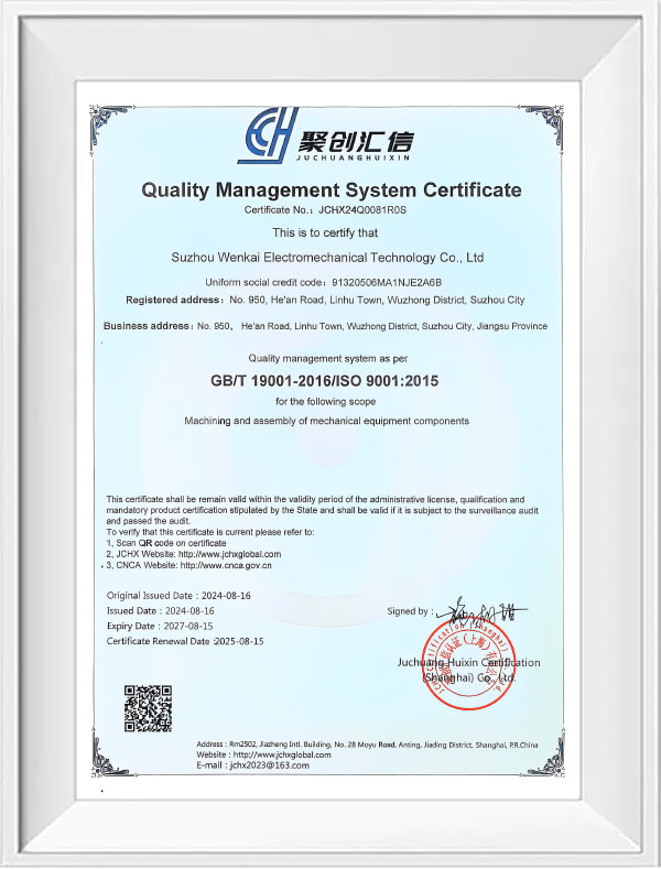
Quality control follows a full-process system under ISO 9001:2015 certification: incoming raw material verification, in-process inspection and final outgoing inspection. The plant uses three coordinate measuring machines, precision height gauges and video measuring machines. For threaded parts, the drawing's thread class and any gauging requirements determine the acceptance method; where a sealing function exists, the surface finish and runout of sealing features are checked against the drawing limits.
Prototype, Small Batch and Series Production
Connector development often goes through several iterations before sealing performance is confirmed. We support prototype machining and small-batch production from drawings, CAD models or existing samples, and we also provide series production once the design is frozen. At the prototype stage the priority is confirming thread fit, sealing geometry and material behavior; at the series stage the priority shifts to process stability, batch-to-batch consistency and inspection documentation.
If the project is still at the validation stage, we recommend starting with a small batch of machined samples to confirm thread fit, sealing behavior and assembly compatibility before the full production quantity is committed.
Information We Use to Prepare Your Proposal
For a threaded joint or connector, a complete drawing is the fastest way to obtain an accurate proposal. Where no drawing exists, a physical sample together with the material grade and application context is sufficient for us to assess the part and prepare a quotation.
| Information required | What it defines |
|---|---|
| 2D drawing with thread callouts | Thread standard, size, class, length and gauging requirement |
| 3D model (STEP/IGES) | Port positions, wall thickness and complex geometry |
| Material grade and condition | Machinability, cost, corrosion and pressure performance |
| Sealing and surface requirements | Surface finish, flatness, deburring and passivation needs |
| Quantity and delivery target | Prototype, small-batch or series process planning |
| Application or assembly context | Media, pressure, temperature and assembly method |
If the drawing leaves a requirement undefined — for example a missing thread class or an unspecified sealing-surface finish — we identify the ambiguity during the quotation stage and confirm a suitable interpretation before machining begins. This avoids costly assumptions and keeps the acceptance criteria aligned with the intended function.
Frequently Asked Questions
Which thread standards do you machine for threaded joints and connectors?
We machine the thread standard and fit class shown on the drawing. Metric ISO threads, UN/UNF/UNC series, and BSP/BSPT or NPT pipe threads are all routine in CNC turning practice. Because the callout defines the tooling and inspection method, we ask for the thread standard, size, class and thread length to be marked clearly.
Can you produce a part with an internal thread on one end, an external thread on the other and a hex in between?
Yes. This is a typical adapter or union geometry. The part is machined around a defined datum, and the drawing should specify the concentricity or runout between the two threads, the hex and any sealing seat. That relationship is often the most important functional requirement, so we confirm it during process planning.
Do you accept existing samples as the basis for a quotation?
Yes. Our custom machining service works from drawings, samples or both. With a sample, we measure the existing geometry and confirm the material and heat-treatment condition before preparing our proposal. A drawing or 3D model is still helpful, but a sample together with application details is enough to start the discussion.
How do you verify thread quality before delivery?
Our plant operates an ISO 9001:2015 quality system with full-process inspection. For threaded parts we confirm the pitch-diameter fit class and sealing-related requirements identified on the drawing, using the inspection equipment appropriate to the feature — including our coordinate measuring machines and precision measuring instruments. Inspection results are documented with the batch.
What production quantities do you support?
We support prototype, small-batch and series production, and our process plan is matched to the quantity. Prototype runs help confirm thread fit and sealing performance; series runs focus on process stability, batch-to-batch consistency and documented quality control.



